
Chapter One Physics Notes
Physics Form One
Introduction to Physics
Science in our lives
Scientists are people trained in science and who practice the knowledge of science.
We require people in industries to work as engineers, technicians, researchers, in hospitals as doctors, nurses and technologists.
Science gives us powerful ideas, instruments and methods which affect us in our daily lives.
Scientific methods
1. A laboratory is a building specifically designed for scientific work and may contain many pieces of apparatus and materials for use.
2. A hypothesis is a scientific fact or statement that has not been proven or experimented.
3. A law or principle is a scientific fact or statement that has been proven and experimented to be true for all conditions.
4. A theorem is a fact or statement that is true and proven but applicable under specific conditions.
What is physics?
Physics is a Greek word meaning nature hence it deals with natural phenomena.
Physics is therefore a science whose objective is the study of components of matter and their mutual interactions.
Physics is also defined as the study of matter and its relation to energy.
A physicist is able to explain bulk properties of matter as well as other phenomena observed.
Branches of physics
1. Mechanics – the study of motion of bodies under the influence of force.
2. Electricity – this deals with the movement of charge from one point to another through a conductor.
3. Magnetism – the study of magnets and magnetic fields and their extensive applications.
4. Thermodynamics / heat – this is the study of the transformation of heat from one form to another.
5. Optics –the study of light as it travels from one media to another.
6. Waves – the study of disturbances which travel through mediums or a vacuum.
7. Particle physics
8. Nuclear physics
9. Plasma physics
Relation of physics to other subjects
Since physics enables us to understand basic components of matter and their mutual interactions it forms the base of natural science.
Biology and chemistry borrow from physics in explaining processes occurring in living things and organisms.
Physics also provides techniques which are applied almost every area of pure and applied science i.e.
meteorology, astronomy etc.
Career opportunities in physics
1 Engineering – civil
- Electrical
- Mechanical
- Agricultural
- Environmental
- Chemical
- Computer2. Meteorology
3. Surveying
4. Geology
5. Astronomy
NOTE: – all science based careers i.e. doctors, nurses, technologists, engineers, pharmacists etc. need physics as a true foundation.
Basic laboratory safety rules
1. Proper dressing must be observed, no loose clothing, hair and closed shoes must be worn.
2. Identify the location of electricity switches, fire-fighting equipment, first aid kit, gas and water supply systems.
3. Keep all windows open whenever working in the laboratory.
4. Follow all instructions carefully and never attempt anything in doubt.
5. No eating or drinking allowed in the laboratory.
6. Ensure that all electrical switches, gas and water taps are turned off when not in use.
7. Keep floors and working surfaces dry. Any spilla ge must be wiped off immediately.
8. All apparatus must be cleaned and returned in the correct location of storage after use.
9. Hands must be washed before leaving the laboratory.
10. Any accidents must be reported to the teacher immediately.
Chapter Two
Measurement
In order to measure we need to know or define the quantity to be measured and the units for measuring it.
In 1971 a system known as the International System of Units (Systeme’ Internationale) and seven basic units were agreed upon as follows. Other quantities can be obtained from these basic quantities and are referred to as derived quantities.
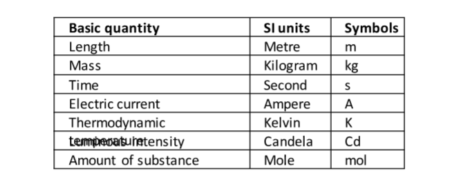
LengthThis is the measure of distance between two points in space. The SI unit for length is the metre (m).Therefore 1 km = 1000 m
1 Hm = 100 m
1 Dm= 10 m
1 mm = 0.001 m
Length is measured using a metre rule (100 cm), tape measure (100 m, 300 m, 500 m)
Area
This is the measure of the extent of a surface. It is a derived quantity of length. Its SI units are square metres (m2). Other units are cm2, km2, etc.
Formulas are used to determine areas of regular bodies while for irregular bodies an approximation of area is used.
Volume
This is the amount of space occupied by matter. The SI units for volume is cubic metre (m3). Other sub-multiples are cm3, mm3 and l.
Hence 1 m3 = 1,000,000 cm3 and 1l= 1,000 cm3. Volume can be measured using a measuring cylinder, eureka can, pipette, burette, volumetric flask, beaker, etc.
Mass
This is the quantity of matter contained in a substance . Matter is anything that occupies space and has weight. The SI unit for mass is the Kilogram (kg).
Other sub-multiples used are grams (g), milligrams (mg) and tonnes (t). 1 kg = 1,000 g = 1,000,000 mg=100 tonnes. A beam balance is used to measure mass.
Density
This is mass per unit volume of a substance. It is symbolized by rho (ρ) and its SI units are kg/m3.
Density = mass / volume.
Examples
1. A block of glass of mass 187.5 g is 5.0 cm long, 2.0 cm thick and 7.5 cm high. Calculate the density of the glass in kgm -3.
Solution
Density = mass / volume = (187.5 /1000) /(2.0 × 7.5 × 5.0 /1,000,000) = 2,500 kgm-3.
2. The density of concentrated sulphuric acid is 1.8 g/cm 3. Calculate the volume of 3.1 kg of the acid.
Solution
Volume = mass / density = 3,100 / 1.8 = 1,722 cm3 or 0.001722 m3.
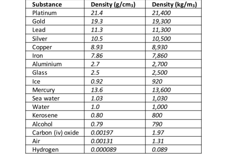
The following is a list of dens ities of some common substances
ExampleThe mass of an empty density bottle is 20 g. Its mass when filled with water is 40.0 g an d 50.0 g when filled with liquid X. Calculate the density of liquid X if the density of water is 1,000 kgm-3.
Solution
Mass of water = 40 – 20 = 20 g = 0.02 kg.
Volume of water = 0.02 / 1,000 = 0.00002 m3. Volume of liquid = volume of bottle
Mass of liquid = 50 – 20 = 30 g = 0.03 kg
Therefore density of liquid = 0.03 / 0.00002 = 1,500 kgm-3
Relative density
This is the density of a substance compared to the density of water.
It is symbolized by (d) and has no units since it’s a ratio.
Relative density (d) = density of substance / density of water. It is measured using a relative density bottle
Example
The relative density of some type of wood is 0.8. Find the density of the wood in kg/m 3.
Solution
Density of substance = d × density of water
Density of subs tance = 0.8 × 1,000 = 800 kgm-3
Densities of mixtures
We use the following formula to calculate densities of mixtures
Density of the mixture = mass of the mixture / volume of the mixture
Example
100 cm3 of fresh water of density 1,000 kgm-3 is mixed with 100 cm3 of sea water of density 1030 kgm-3.
Calculate the density of the mixture.
Solution
Mass = density × volume
Mass of fresh water = 1,000 × 0.0001 = 0.1 kg
Mass of sea water = 1030 × 0.0001 = 0.103 kg
Mass of mixture = 0.1 + 0.103 = 0.203 kg
Volume of mixture = 100 + 100 = 200 cm3 = 0.0002 m3
Therefore density = mass / volume = 0.203 / 0.0002 =1,015 kg/m3.
Time
This is a measure of duration of an event . The SI unit for time is the second (s). Sub- multiples of the second are milliseconds, microseconds, minute, hour, day, week and year.
It is measured using clocks, stop watches, wrist watches, and digital watches.
Accuracy and errors
Accuracy is the closeness of a measurement to the correct value of the quantity being measured.
It is expressed as an error.
An error is therefore the deviation of measurement to the correct value being measured.
The smaller the error the accurate the measurement.
% error = (sensitivity / size measured) × 100.
Chapter Three
Forces.
Force is a push or a pull. Force is therefore that which changes a body’s state of motion or shape.
The SI unit for force is Newton (N). It is a vector quantity. It is represented by the following symbol.
Types of forces1. Gravitational force –this is the force of attraction between two bodies of given masses.
– Earth’s gravitational force is the force which pulls a body towards its center. This pull of gravity is called weight.
2. Force of friction – this is a force which opposes the relative motion of two surfaces in contact with each other. Friction in fluids is known as viscosity.
3. Tension force – this is the pull or compression of a string or spring at both its ends.
4. Upthrust force – this is the upward force acting on an object immersed in a fluid.
5. Cohesive and adhesive forces – cohesive is the force of attraction of molecules of the same kind while adhesive is the force of attraction of molecules of different kinds .
6. Magnetic force – this is a force which causes attraction or repulsion in a magnet.
7. Electrostatic force – this is the force of attraction or repulsion of static charges.
8. Centripetal force – this is a force which constrains a body to move in a circular orbit or path.
9. Surface tension – this is the force which causes the surface of a liquid to behave like a stretched skin. This force is cohesive.
Factors affecting surface tension
a) Impurities – they reduce the surface tension of a liquid i.e. addition of detergent.
b) Temperature – rise in temperature reduces tension by weakening inter-molecular forces.
Mass and weight.
Mass is the amount of matter contained in a substance while weight is the pull of gravity on an object.
The SI unit for mass is the Kg while weight is the newton (N).
Mass is constant regardless of place while weight changes with place.
The relationship between ma ss and weight is given by the following formula, W = mg where g = gravitational force.
Differences between mass and weight Mass
- It is the quantity of matter in a body
- It is measured in kilograms
- It is the same everywhere
- It is measured using a beam balance
- Has magnitude only Weight
- It is the pull of gravity on a body
- It is measured in newton’s
- It changes from place to place
- Measured using a spring balance
- Has both magnitude and directionExample
An astronaut weighs 900 N on earth. On the moon he weighs 150 N. Calculate the moons’ gravitational strength. (Take g = 10 N/kg).
Solution
Moons’ gravitational strength = weight of astronaut on the moon / mass of astronaut. = 150 / 90 = 1.67 Nkg-1.
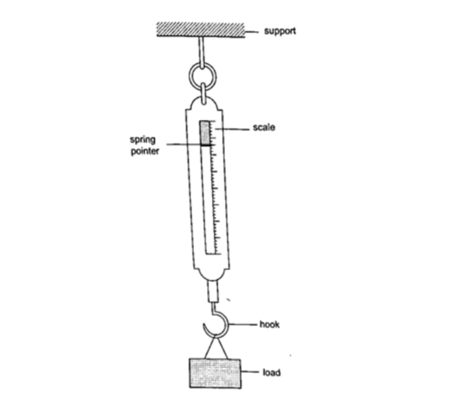
Measuring force
We use a spring balance to measure force. A spring balance is an instrument that uses the extension of a spring to measure forces.
ExampleThe length of a spring is 16.0 cm. its length becomes 20.0 cm when supporting a weight of 5.0 N. calculate the length of the spring when supporting a weight of:
a) 2.5 N
b) 6.0 N
c) 200 N
Solution
5N causes an extension of 4.0 cm, therefore 1.0 cm causes an extension of 4 /5 = 0.8 cm.
a) 2.5 N => 2.5 × 0.8 = 2.0 cm therefore length becomes = 16.0 + 2.0 = 18.0 cm.
b) 6.0 N => 6.0 × 0.8 = 4.8 cm therefore length becomes = 16.0 + 4.8 = 20.8 cm.
c) 200 N => 200 × 0.8 = 160.0 cm therefore length becomes = 16.0 + 160.0 = 176.0 cm.
Vector and scalar quantities
A scalar
quantity is a quantity which has magnitude (size) only . Examples are distance, mass, speed
A vector
quantity is a quantity which has both magnitude and direction. Examples are displacement, weight, velocity.
chapter Four
Pressure
Pressure is defined as the force acting normally (perpendicularly) per unit area .
The SI units for pressure is newton per metre squared (N/m2).
One Nm-2 is known as one Pascal (Pa).
Pressure = normal force / area or pressure = thrust / area . Another unit for measuring pressure is the bar. 1 bar = 105 N/m2. 1 millibar = 100 N/m2.
Calculating pressure
Examples
1. A rectangular brick of weight 10 N, measures 50 cm × 30 cm × 10 cm.
calculate the values of the maximum and minimum pressures which the block exert when resting on a horizontal table.
Solution
Area of the smallest face = 0.3 × 0.1 = 0.03 m2. Area of the largest face = 0.5 × 0.3 = 0.15 m2.
Maximum pressure = 10 N / 0.03 = 3.3 × 10² N/m2. Minimum pressure = 10 N / 0.15 = 67 N/m2.
2. A man of mass 84 kg stands upright on a floor. If the area of contact of his shoes and the floor is 420 cm2, determine the average pressure he exerts on the floor. (Take g = 10 N/Kg)
Solution
Pressure = force / area = 840 / 0.042 = 20,000 Nm-2.
Pressure in liquids.
The following formula is used to determine pressure in liquids.
Pressure = h ρ g, where h – height of the liquid, ρ – density and g – is force of gravity.
Examples
1. A diver is 10 m below the surface of water in a dam. If the density of water is 1,000 kgm -3, determine the pressure due to the water on the diver. (Take g = 10 Nkg-1)
Solution
Pressure = h ρ g = 10 × 1000 × 10 = 100,000 Nm-2.
2. The density of mercury is 13,600 kgm-3. Determine the liquid pressure at a point 76 cm below the surface of mercury. (Take g = 10 Nkg-1)
Solution
Pressure = h ρ g = 0.76 × 13,600 × 10 = 103,360 Nm-2
. 3. The height of the mercury column in a barometer is found to be 67.0 cm at a certain place.
What would be the height of a water barometer at the same place? (Densities of mercury and water are 1.36 × 10⁴ kg/m3 and 1.0 × 10³ kg/m3 respectively.)
Solution
Let the pressure due to water be h1ρ1g1 = h ρ g, hence;
h1 = h ρ / ρ1= (6.7 × 10-1) × (1.36 × 104) = 911.2 cm or 9.11 m.
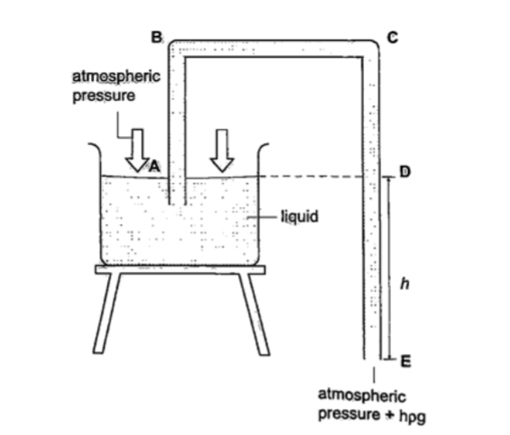
U-tube manometer
It is a transparent tube bent into U-shape. When a liquid is poured into a u-tube it settles at equal level since pressure depends on height and they s hare the same bottom.
Consider the following diagrams;
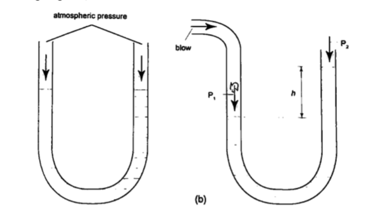
For the levels to differ the pressure P1 must be greater than P2, henceP1 = P2 + hρg.
If P1 is the lung pressure, P0 is the atmospheric pressure, then if the difference is ‘h’ then lung pressure can calculated as follows.
P1 = P0 + hρg.
Example
A man blows into one end of a U-tube containing water until the levels differ by 40.0 cm. if the atmospheric pressure is 1.01 × 10⁵ N/m2 and the density of water is 1000 kg/m3, calculate his lung pressure.
Solutionp Lung pressure = atmospheric Pressure + liquid pressure
P1 = P0 + hρg. Hence P1 = (1.01 × 10⁵) + (0.4 × 10 × 1000) = 1.05 × 10⁵ N/m2.
Measuring pressure
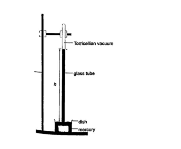
1. Simple mercury barometer– it is constructed using a thick walled glass tube of le ngth 1 m and is closed at one end. Mercury is added into the tube then inverted and dipped into a dish containing more mercury. The space above the mercury column is called torricellian vacuum.
The height ‘h’ (if it is at sea level) would be found to be 760 mm.
Atmospheric pressure can be calculated as, P = ρ g h =>where ρ (mercury)- 1.36 × 10⁴ kg/m3, g- 9.81 N/kg, h- 0.76 m. Then P = (1.36 × 104) × 9.81 × 0.76 = 1.014 × 10⁵ Pa.
NOTE– this is the standard atmospheric pressure, sometimes called one atmosphere. It is approximately one bar.
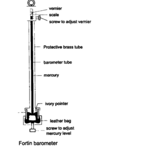
2. Fortin barometer–this is a more accurate mercury barometer. The adjusting screw is adjusted first to touch the mercury level in the leather bag.
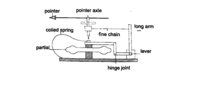
3. Aneroid barometer– increase in pressure causes the box to contract, the movements are magnified by the system of levers and is transmitted to the pointer by the fine chain and this causes the pointer to move.The scale is suitably calibrated to read pressure. Since pressure falls or rises as altitude falls or rises, the pointer can also be calibrated to read altitude.
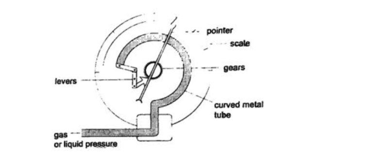
4. Bourdon gauge– it is also called gauge pressure and is used in gas cylinders. When air is blown into the rubber tube, the curved metal tube tries to straighten out and this causes movement which is transmitted by levers and gears attached to a pointer. This gauge can measure both gas and liquid pressure.
Examples1. The height of the mercury column in a barometer is found to be 67.0 cm at a certain place.
What would be the height of a water barometer at the same place? (densities of mercury – 1.36 × 10⁴ kg/m3 and water- 1.0 × 10³ kg/m3).
Solution
Let the pressure due to water be h1 ρ1 g1 and that of water be h ρ g. Then h1 ρ1 g1 = h ρ g. Hence h1 = (6.7 × 10-1) × (1.36 × 104) / 1.0 × 103 = 911.2 cm or 9.11 m.
Application of pressure in gases and liquids.
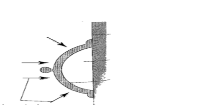
1. Rubber sucker– this is a shallow rubber cap. Before use it is moistened to get a good seal then pressed firmly on a smooth surface so that the air inside is pushed out. The atmospheric pressure will then hold it firmly against the surface as shown below.
They are used by printing machines to lift papers, lifting glass panes, heavy metal sheets etc.
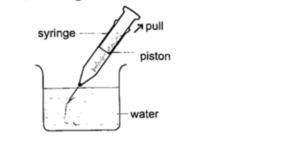
2. Drinking straw– when a liquid is drawn using a straw air is sucked through the straw to the lungs. This leaves the space in the straw partially evacuated. The atmospheric pressure pushing down the liquid in the container becomes greater than the pressure inside the straw and this forces the liquid into your mouth.3. The syringe– they work in the principle as the straw. They are used by the doctors in hospitals for giving injections.
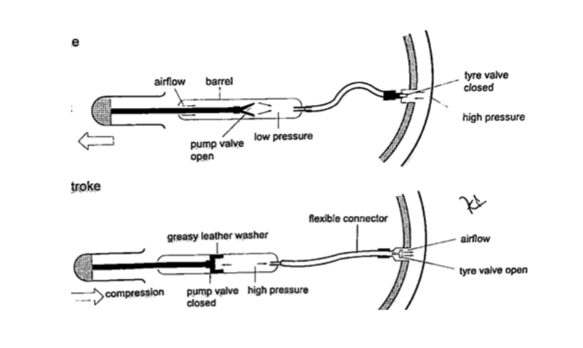
4. Bicycle pump– it uses two valves, one in the pump (greasy leather) and the other in the tire. When the handle is pushed in, the pressure inside the barrel becomes greater than the one in the tire and this pushes air inside.The valve in the tire is made such that air is locked inside once pumped.
5. The siphon– it is used to empty tanks which may not be easy to empty by pouring their contents out.The tubing must be lowered below the base of the tank.
The liquid flows out due to pressure difference caused by the difference in height ( h ρ g).
6. Lift pump.7. Force pump.
Transmission of pressure in liquids and gases.
It was first recognized by a French mathematician and physicist called Blaise Pascal in the 17th century.
Pressure is equally distributed in a fluid and equally transmitted as shown in
the following,
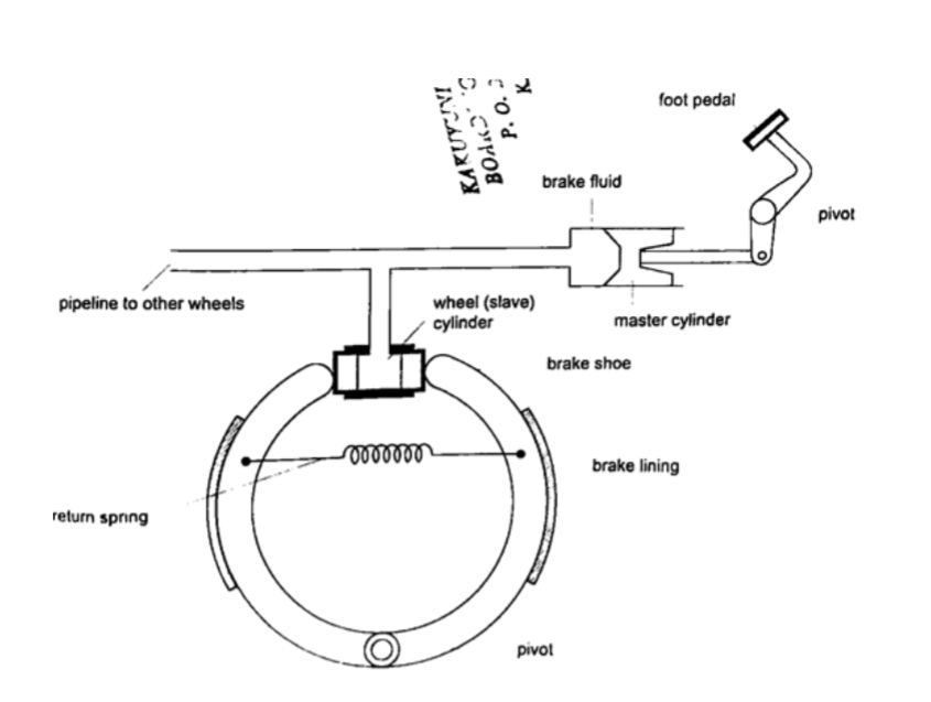
a) Hydraulic brake system– the master cylinder transmits pressure to the four slave cylinders on each wheel.
The cylinders contain brake fluid.
Fluid is used because liquids are almost incompressible.
When force is applied in the pedal the resulting pressure in the master cylinder is transmitted to the slave cylinders.
This forces the piston to open the brake shoes which then pushes the brake lining against the drum.
This force the rotation of the wheel to slow down. It is important to note that pressure is equally distributed in all wheels so that the car doesn’t pull or veer to one side.
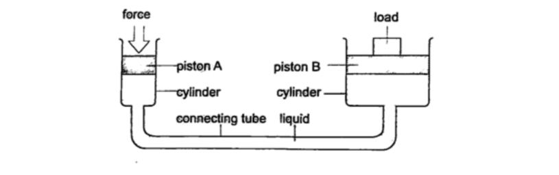
b) Hydraulic press– it consists of two pistons with different cross -sectional areas. Since pressure is transmitted equally in fluids, when force is applied in one piston it is transmitted to the other piston.The smaller piston is called the force while the bigger piston is called the load.
They are used to lift heavy loads in industries, bending metals and sheets etc.
Examples1. The area of the smaller piston of a hydraulic press is 0.01 m 2 and that of the bigger piston is 0.5 m2. If the force applied to the smaller piston is 2 N, what force is transmitted to the larger piston?
Solution
Pressure = force / area – hence P = 2 / 0.01 = 200 Pa.
Force = Pressure × Area = 200 × 0.5 = 100 N.
2. The master cylinder piston in a car braking system has a diameter of 2.0 cm.
The effective area of the brake pads on each of the four wheels is 30 cm 2.
The driver exerts a force of 500 n on the brake pedal. Calculate.
a) The pressure in the master cylinder.
b) The total braking force in the car.
Solution
a) Area of the master cylinder – π r2 = 3.14 cm2
Pressure = force /area = 500 / 3.14 × 10-4 = 1.59 × 10⁶ N/m2
b) Area of brake pads = (30 × 4) cm2. Since pressure in the wheel cylinder is the same as in the master cylinder)2
F = Pressure × Area = (1.59 × 106) × (120 × 10-4) = 1.91 × 10⁴ N.
Chapter Five
Particulate Nature of Matter.
States of matter
Matter is anything that occupies space. Matter exists in three states: solids, liquids and gases.
Matter can be changed in various ways which includes physical, chemical and nuclear changes.
a) Physical changes– they are normally reversible and no new substances formed. Examples are;
(i) Change of state such as melting and vaporization
(ii) Thermal expansion due to heating
(iii) Dissolving solids in liquids
(iv) Magnetizing
(v) Charging electrically
b) Chemical changes– they are irreversible and new substances are formed Examples are;
(i) Changes caused by burning
(ii) Changes occurring in some chemicals due to heating e.g. mercuric oxide
(iii) The reactions resulting from mixing chemicals to form other substances.
c) Nuclear changes– these are changes occurring in nuclear substances which give off some particles i.e. Uranium and Radium. As this happens they change into other substances.
Particulate nature of matter
Matter is made up of millions of tiny particles which cannot be seen with naked eyes. These particles are called atoms and are made up of sub-atomic particles called protons, neutrons and electrons.
Atoms join together to form molecules.
Movement of particles
Particles move from one region to another by the process of diffusion. Diffusion is the movement of molecules from regions of high concentration to regions of low concentration until an equilibrium is reached or achieved. Gases diffuse faster or readily than liquids.
The rate of diffusion depends on the manner of arrangement of individual particles.
Solids
Individual atoms in solids have a small space between them hence their forces of attraction are very strong.
They vibrate in their fixed positions and this gives solids a fixed shape.
Liquids
Forces of attraction between liquid molecules are not as strong as in solids where motion is not restricted. They collide with each other as they move about.
They take the shape of the container they are put in hence have no definite shape.
Gases
Molecules of atoms in gaseous state are further apart experiencing very small forces of attraction.
This makes them almost completely free from each other.
We say they are independent in space. Gases have no definite shape and volume but they take up the space and volume of the container they are put in.
Chapter Six
Thermal Expansion.
Introduction
Temperature is the degree of hotness or coldness of a body. Both Celsius scale (0C) and Kelvin scale (thermodynamic scale) are used to measure temperature.
The Kelvin scale is also known as the absolute scale temperature and is measured from absolute zero (0 K).
Expansion of solids
When solids are heated they expand. The expansion is so small such that we can’t see them.
The following experiments will demonstrate actual expansion of solids.
Experiment 1:- Ball and ring experiment
Procedure
1. Obtain a ball and ring apparatus.
2. Pass the ball through the ring at room temperature and observe that it easily slips through.
3. Heat the ball using a Bunsen burner for one minute.
4. Try to pass the ball through the ring and observe what happens.
5. Let it cool for some time and try passing the ball again.
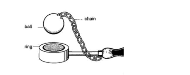
DiscussionWhen the ball is heated it expands and increases in diameter. This makes the ball not to pass through the ring. After cooling it is found that the ball slips through the ring easily again.
Experiment 2:
– The bar-breaker
Procedure
1. Try and break the cast-iron pin with your hands. Can you? (A bar-breaker is a strong iron frame which holds a steel bar fitted with a wing- nut. The other end is held by cast-iron pin as shown below).
2. Tighten the nut but do not break the pin.
3. Heat the bar strongly using two Bunsen burners as you keep tightening the nut. 4. Continue heating for another five minutes then let it cool.
5. Observe what happens.
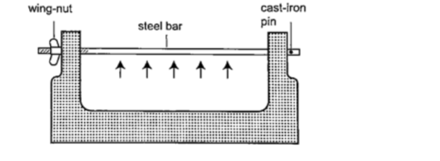
DiscussionWhen the bar cools the cast-iron pin breaks. This shows that as the bar cools it contracts and strong forces pull against the pin.
These forces makes the pin to break.
Experiment 3:- Heating a bimetallic strip
Procedure
1. Heat a brass-iron bimetallic strip using a Bunsen burner and make sure it is heated evenly.
2. Observe what happens after a short while.
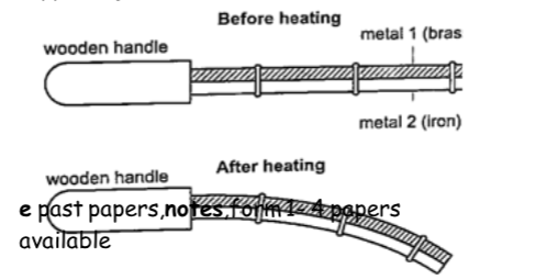
DiscussionWhen a brass-iron bimetallic strip is heated it bends towards the iron.
This means that brass expands more than iron and this causes the strip to bend towards the iron side.
This shows that different materials expand at different rates when heated.
Applications of the expansion of solids
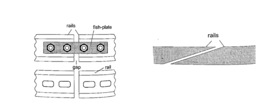
1. Construction of railway lines
– an expansion joint is allowed between any two rails to accommodate expansion.
A fish plate is used to join two rails. Modern railway system use the overlapping joint at the end of rails.
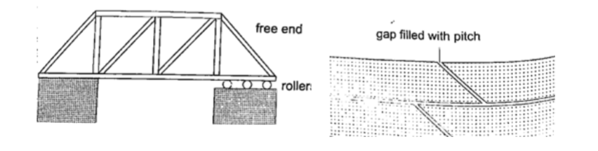
2. Construction of bridges and roof tops (steel girders)– for bridges one side has rollers while the other is fixed to allow for expansion.Concrete slabs are also laid on the ground leaving space filled with pitch to allow for expansion.
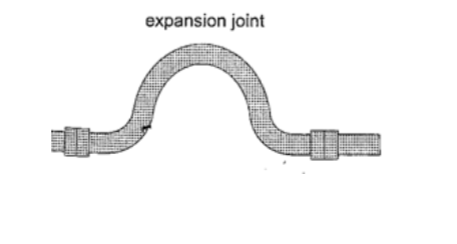
3. Hot water pipes– pipes carrying hot water (steam) from boilers are fitted with expansion joints for expansion.
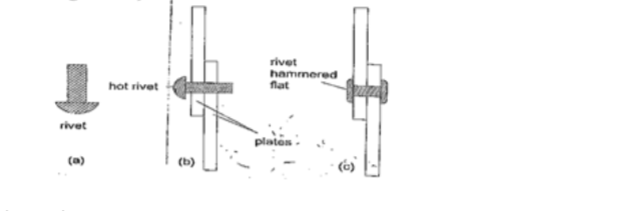
4. Riveting– used to join two pieces of metal together i.e. bimetallic strips, car bodies, drums etc.
Fitting rail cart wheel using heat uses the principle of rivets. Bimetallic strips are used in thermostats (control temperature) – electric iron box, alarm systems, car flasher units etc.
Expansion of liquids and gases.Expansion of liquids.
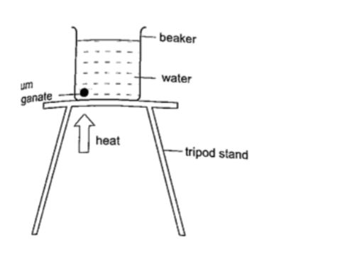
Liquids expand more than solids so it is easy to observe and see clearly as they expand. We use the hot water bottle to demonstrate the expansion of water. Water is put in the bottle as shown below.
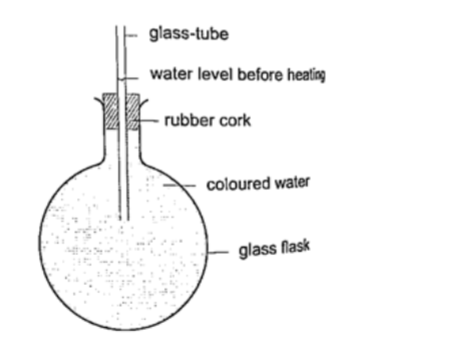
When the bottle is immersed in hot water, initially there i s a drop in the level of water in the glass tube then it steadily rises after a while.This shows that liquids expand with increment in volume as shown by the hot water bottle.
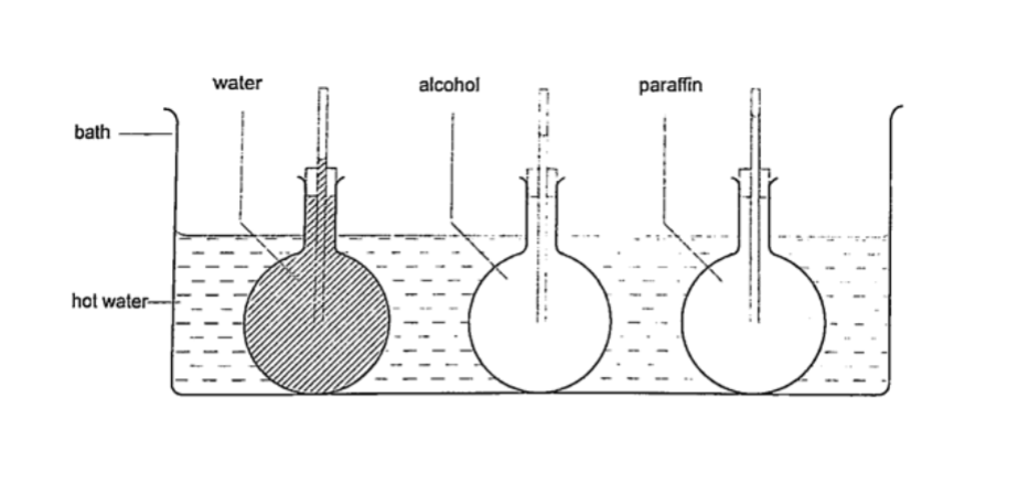
Different liquids expand at different rates as shown below.
Expansion of gasesThey are the easiest to observe since they expand the most.
Experiment: – Expansion of air
Procedure
1. Obtain an empty 500 ml round bottomed flask fitted with a cork and a glass tubing.
2. Place a beaker with some water on a bench.
3. Rub your hands together thoroughly and place them on the flask and place it in the water as shown.
4. Observe what happens.
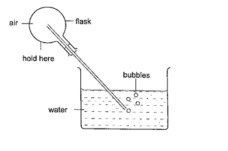
DiscussionThe heat produced by the hands makes the air inside the flask to expand.
This makes the volume to increase and therefore force the excess air out as bubbles.
Applications of the expansion of gases and liquids.
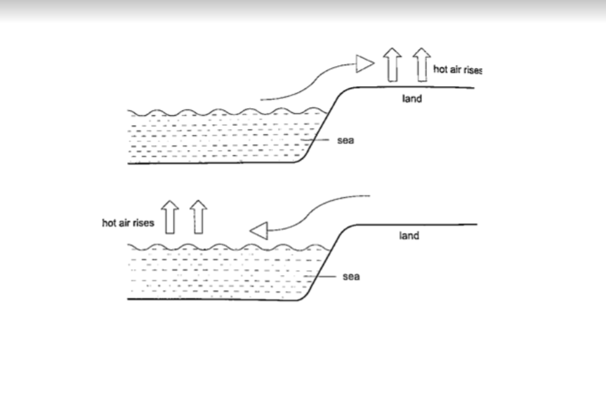
1. Land and sea breeze
– during the day the land is heated by the sun causing the air above it to expand.
The air becomes less dense therefore it rises. The space left is quickly filled by another cool air (generally from the sea since the land gets hot faster).
This causes a cool breeze form the sea during the day. At night the land loses heat faster than the sea.
The air above the sea rises since it is less dense and cool air from the land rushes to fill the gap.
This causes a breeze blowing from the land to the sea.
Thermometers1. Liquid-in-glass thermometer–this applies to the expansion of a liquid in a thin-walled glass-tube. The liquid moves up the tube when the bulb is heated.
The liquid must be a good conductor, visible and be able to contract and expand quickly and uniformly over a wide range of temperatures. It should also not stick on the sides of the tube. Liquids commonly used are mercury and coloured alcohol.
The scale is obtained by choosing two temperature points called fixed points.
In Celsius lower point is taken to be 0oC (when placed in ice) and the upper point as 100oC (boiling steam).
The two points are therefore divided into 100 equal parts (calibration). The melting and boiling points of both mercury and alcohol are (-39 oC – 357 oC) and (-112 oC – 78 oC) respectively.
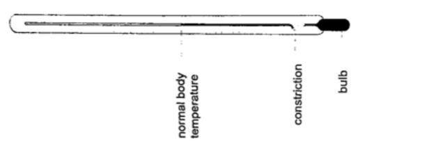
2. Clinical thermometer – this is a special type of mercury-in-glass thermometer used to measure body temperature. Since body temperature is normally 37 oC the scale is only a few degrees below and above 37oC.
It has a constriction which prevents mercury from going back after expansion for convenient reading of temperature.
This thermometer has a narrow bore for greater sensitivity and accuracy.
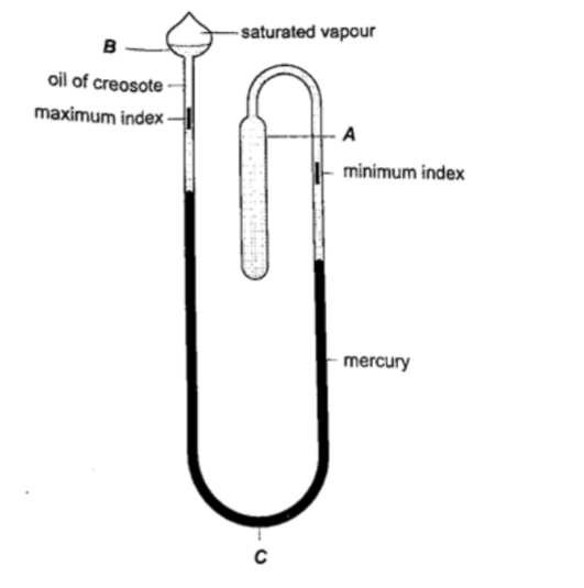
3. Six’s maximum and minimum thermometer – it is used to measure temperature of surroundings of an area or a place.It can record both maximum and minimum temperatures attained.
Consists of a large bulb (A) containing oil of creosote connected to U-shaped stem which connects to a second bulb (B) containing the same liquid.
The base (C) contains a thin thread of mercury. The range of this thermometer is between -20 oC and 50 oC. After each reading the indices are pulled down to the level of mercury by use of a magnet.
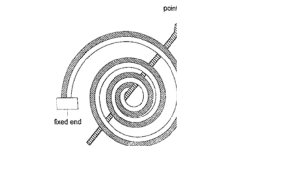
4. Bimetallic thermometer– it is made up of a bimetallic strip with one end fixed and the other connected to a pointer.Metals used are usually brass and invar.
As temperatures increase the strip unwinds and moves the pointer over a calibrated scale. It is used to measure high temperatures.
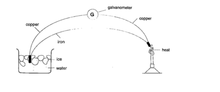
5. Thermocouple thermometer– thermocouple is a junction made of copper and iron looped at both ends. In practice a sensitive millivoltmeter is used instead of a galvanometer.A cold junction is maintained in melting ice (00C) while the other junction is heated steadily. This thermometer does not apply the principle of expansion.
Unusual expansion of water.If water is heated let’s say from -150C it expands normally like any solid but only up to 0oC. At this point it starts to melt and it contracts.
This contraction will be observed up to 4 0C.
When heated further water starts to expand up to boiling point.
This is the unusual expansion of water.
This makes the top of water to freeze (0C) in temperate countries allowing the one below to remain liquid (40C). This supports marine life during winter.
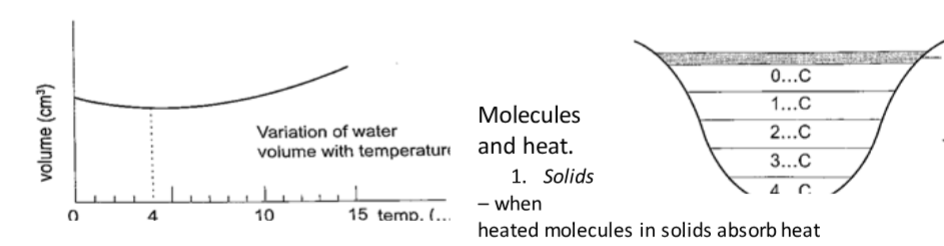
Molecules and heat.1. Solids– when heated molecules in solids absorb heat energy and vibrate.
They push against one another and this causes expansion. Further expansion may result to collapse as melting in ice.
2. Liquids – besides vibrating particles in a liquid move short distances. As they move they collide by hitting each other and this results to more expansion.
For boiling to occur molecules absorb enough energy to be able to escape from the liquid.
3. Gases – individual particles are free of one another and in rapid motion.
When heated there are collisions with the walls of the container. This results to high pressure in the container.
Chapter Seven
Heat Transfer.
Heat is transferred in matter through the following methods: conduction, convection and radiation.
Conduction
This is the transfer of heat in solids. The rate of conduction depends on
1. Amount of temperature – the higher the temperature the higher the rate of transfer.
2. Cross-sectional area – the larger the cross-sectional area the higher the transfer.
3. Length of material – the shorter the material the higher the rate of transfer.
4. Type of material – different materials transfer heat at different rates.
Good and bad conductors
Conductivity is the ability of a material to conduct heat.
Good conductors of heat are those materials which are able to transfer heat easily and steadily.
Bad conductors are those which do not conduct heat.
Experiment:
Comparing thermal conductivity of metals
Procedure
1. Obtain four identical rods of copper, iron, aluminium and brass.
2. At one end of each rod attach a matchstick using paraffin wax and let it solidify.
3. Place the rods on a tripod stand with the free ends close to one another as shown.
4. Heat the free ends strongly with a Bunsen burner.
5. Observe what happens.
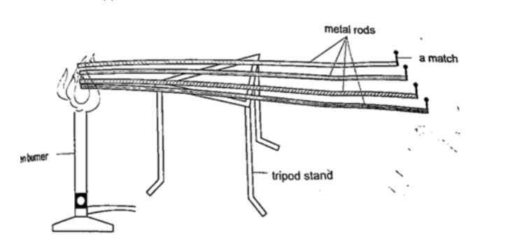
DiscussionWhen done correctly and carefully the matchsticks will fall off in the following order: copper, aluminium, brass and finally iron. This shows that different metals conduct heat at different rates.
NOTE – on a cold morning a metallic chair would feel cold compared to a wooden chair at the same temperature, this is because the metal lic chair absorbs heat from your body as opposed to wood which is a bad conductor of heat.
Applications of conductors
Good conductors
1. They are used to manufacture cooking utensils
2. They are used as liquids suitable for thermometers i.e. mercury
3. Used as heat dumps (metal clips) when soldering delicate components in a circuit board i.e. transistors
Poor conductors
1. Used as insulators in handles of cooking utensils
2. Used in making good winter clothes i.e. wool
3. Hot water cylinders are lagged with fibre -glass since glass is a poor conductor of heat.
4. Houses in cold countries have double walls with air trapped in them to keep them warm.
Convection
This is the transfer of heat through fluids (liquids and gases). This occurs when part of the fluid is heated: they become less dense and rise above the cold fluid. As they move they carry heat with them.
In convection we observe streams of moving fluid called convectional currents.
Convection in air
Experiment: model chimney (smoke box)
Procedure
1. Obtain a model chimney system or construct one as shown
2. Place a lighted candle under one of the chimneys
3. Place a smouldering cloth near the other chimney and observe what happens.
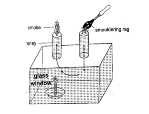
DiscussionSmoke will be seen going into the chimney and coming out through the other c himney. The air above the candle gets heated and rises up the chimney causing convectional currents which carry the smoke out with them.
Experiment: revolving paper-vane
Procedure
1. Make a paper-vane by cutting a thin card as shown
2. Put a string through the hole in the centre and hold it above a lighted Bunsen burner.
3. Observe what happens.
Discussion
As the air above the flame gets heated convectional currents are formed and rise upwards.as these currents brush against the paper-vane it rotates.
Convection in liquids
Experiment:
heating water in a beaker
Procedure
1. Put water in a beaker until it is three quarters full and place it on a tripod stand.
2. Drop a crystal of potassium permanganate through a tube to settle at one corner at the bottom of the flask.
3. Heat the water gently using a Bunsen burner and observe the movement of streams of colour.
DiscussionA stream of colour will be seen moving upwards and downwards again at the other side of the beaker.
This will continue gradually until all the water becomes coloured. This shows that convectional currents also exist in liquids.
Experiment: model of hot water system
Procedure
1. Obtain two flat bottomed flasks and set up the apparatus as shown below.
2. Hold the flasks in place by use of clamp stands.
3. Heat the bottom of the lower flask and observe what happens.
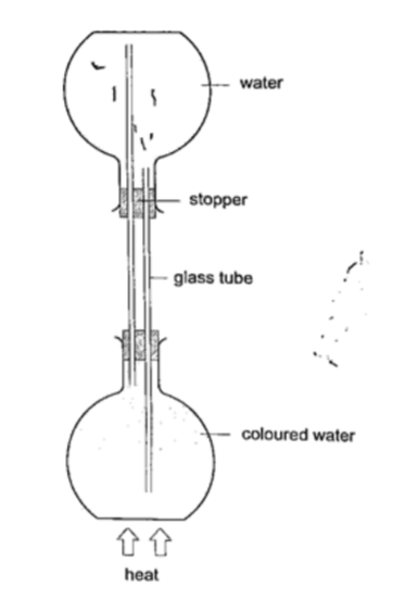
DiscussionWhen the water in the lower flask becomes hot it rises up to the upper flask. After some time the water in the upper flask will become hot due to convectional currents.
Applications of convection
1. Brings about the land and sea breezes.
2. Can be used to explain the weather phenomena.
3. Used in car radiators.
4. Used in immersion water heaters by placing them at the bottom.
Radiation
This is simply the flow of heat from one point to another by means of electromagnetic waves.
Radiation from different surfaces
We use the Leslie cube to determine radiation of different surfaces.
It is a rectangular metal container of square base with small opening at the top.
One side is coated with polished silver, another dull black (candle flame soot), the other grey and the fourth white.
Experiment: Radiation from different surfaces
Procedure
1. Place a Leslie cube on a tripod stand and attach a thermometer on each of the four sides.
2. All thermometers should be at least 5.0 cm form the surface and should read the same temperature.
3. Pour hot water (about 80 0C) until it is full and note the reading of each thermometer after 1 minute.
4. Repeat the above procedure using boiling water (100 0C).
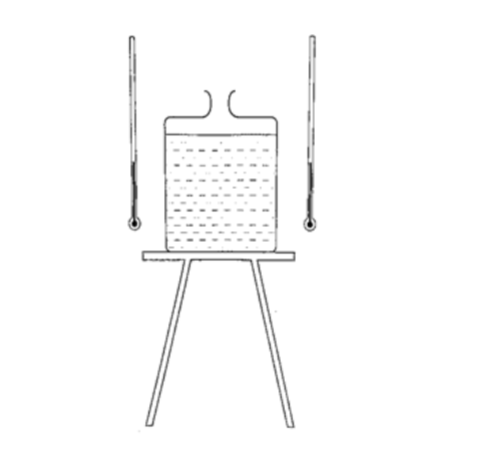
DiscussionThe thermometer against the black surface records the highest temperature, followed by the one on the grey side, then the white surface while the polished side recorded the lowest temperature.
The readings when the water is boiling were higher, indicating that radiation depends on temperature. It also depends on the nature of surface.
Applications of radiation
1. Electric kettles have a chrome coat to reduce radiation.
2. Electric iron are silver coated to minimize radiation.
3. Green houses use radiation (heat trap) to grow crops.
4. Clouds reflect radiation back to the earth hence cloudy nights are warmer than clear nights.
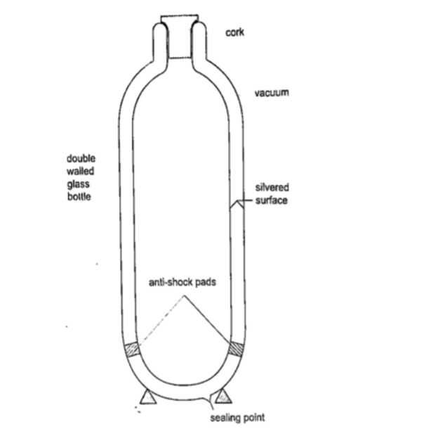
Vacuum flask
It was developed by Sir James Ivarin 1890. It keeps a liquid hot or cold (depends on what is put in).
The liquid stays at the temperature it is poured in either hot or cold.
It has the following principle features;
(i) The vacuum between the double walls
(ii) The two interior walls coated with silver
(iii) Insulating cork supports (anti-shock pads)
(iv) Insulating cork stopper at the top.
Chapter EightRectilinear Propagation and Reflection at Plane Surfaces. Introduction
Objects that produce their own light are known as luminous objects i.e. the sun, torch lamps etc. objects that do not produce their own light are called non-luminous objects i.e. the moon.
Opaque objects are those which do not allow light to pass through them. Translucent materials are those which allow light to pass through them but we cannot see through them i.e. church glass and bathroom glass.
Transparent materials are those which allow light to pass through them and we can see through them i.e. window panes, car windows etc.
A ray is the direction of the path followed by light. A beam is a group of rays travelling together.
Experiment: light travels in straight lines
Procedure
1. Obtain three cardboards with a hole at the center and mount them such that they form a straight line.
2. Arrange them as shown and place a lighted candle at one end and make sure that you can see the flame from the other end.
3. Move any of the cardboards and observe what happens.
Discussion
When one cardboard is displaced or moved slightly the flame cannot be seen at the other end. This shows that light travels in a straight line.
T his principle is applied in the following, Pinhole camera It consists of a closed box with a small hole on one face and a screen of tracing paper/ frosted glass on the opposite face as shown. An image will be formed on the screen.
Since light travels from one point of the object through the hole an image will be formed on the opposite screen of the box.
If the object is near the hole it is magnified while diminished if away from the hole.
Magnification is therefore the ration of the image to object height , expressed as,
Magnification = height of image/ height of object or
= distance of image from pinhole/ distance of object from pinhole
Shadows
Shadows are formed when an opaque object is placed between a source of light and a screen. When the shadow is big a dark patch at the centre is formed (umbra) while a surrounding lighter patch called penumbra is formed.
Eclipses Eclipse of the sun (solar eclipse) This occurs when the moon is between the earth and the earth.
The shadow of the moon falls on the earth’s surface. Sometimes the distance is large for the shadow to reach the earth and when this happens an annular eclipse occurs.
Annular eclipse
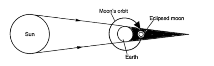
Eclipse of the moon
It is also known as lunar eclipse and occurs when the earth is between the sun and the moon. The shadow of the earth falls on the moon.
Examples1. Calculate the height of a building 300 m away from a pinhole camera which produces an image 2.5 cm high if the distance between the pinhole and the screen is 5.0 cm.
Solution
Object distance = 300 m, image height = 2.5 cm, image distance = 5.0 cm. Object
height/ image height = object distance/ image distance
Object height = (30,000 × 2.5) / 5.0 = 15,000 cm = 150 m.
2. The length of a pinhole camera is 25.0 cm. An object 2.0 cm is placed 10.0 m from the pinhole. Calculate the height of the image produced and its magnification.
Solution
Image height = (image distance × object height) / object distance
= (25 ×200) / 10 = 500 cm or 5 m. Magnification = image distance / object distance = 25 /10 = 2.5
Reflection from plane surfaces
Diffuse and regular reflection
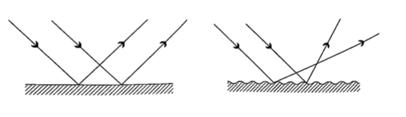
Regular reflection occurs when a parallel beam of light falls on a plane mirror band reflected as a parallel beam. They occur on polished surfaces. A diffuse reflection occurs on rough surfaces where a parallel beam of light is reflected in all directions.
Laws of reflection1. The incident ray, the normal and the reflected ray at the point of incidence must be on the same plane
2. The angle of incidence is equal to the angle of reflection.
I mages formed by reflection from plane surfaces
Characteristics of images formed in a plane mirror
1. The image is the same size as the object
2. The image is the same distance behind the mirror as the object is in front
3. The image is laterally inverted
4. The image is virtual
5. The image is erect.
Location of an image by the non-parallax method
Parallax is the apparent relative motion of two objects due to the movement of the observer.
It only occurs when the objects are at a distance from one another.
This can be used to find the position of images in plane mirrors.
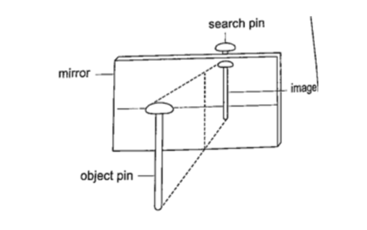
Experiment: To find the position of an image of a pin by non-parallax method
Procedure
1. Obtain a sheet of paper and draw a mirror line
2. Place the mirror on the line as shown
3. Place the pin at least 5 cm from the mirror and obtain another pin (search pin)
4. Move the pin till you get a point where there is no parallax and place your second pin.
5. Measure the distances (both image and object) and confirm your results.
Mirrors at an angleWhen mirrors are placed at an angle several images are obtained depending on the angle between them.
If the angle is 600 the images formed will be five. We use the following formula to find the number of images.
n = (360o / θ) – 1
When mirrors are parallel then the images formed are infinite.
KaleidoscopeIt applies the principle of mirrors at an angle. Consists of two mirrors arranged at an angle of 600 to one another inside a tube.
The bottom has a ground-glass plate with brightly coloured glass for allowing light.
When one observes through the tube five images are seen.
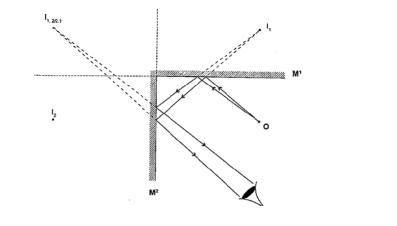
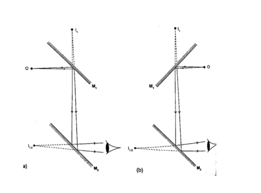
The periscopeThis consists of two mirrors arranged at an angle of 450 as shown. This principle is used in periscopes (prisms) and telescopes.
Chapter NineElecrostatics I.
Some substances get charged when rubbed against other substances i.e. nylon, plastic, paper etc. the charge acquired stays within the body i.e. it does not move and therefore known as electrostatic charge or static electricity. The law of charges – types of charges There are two types of charges i.e. negative and positive charges.
The negative charge consists of electrons which are mobile.
The law of charges in summary states that “like charges repel, unlike charges attract’’.
Just like in magnetism attraction is not a sure way of testing for charge but repulsion because it will only occur if the bodies are similarly charged.
Charges, atoms and electrons
The atom is made up of a central part called the nucleus, containing positively charged ions called protons and outwardly surrounded by negatively charged electrons.
The nucleus also contain the particles called neutrons which are not charged.
When an atom is not charged the number of protons equals the number of electrons.
When a material is rubbed with another i.e. acetate with silk, electrons are transferred from one body to another.
The body accepting or receiving electrons becomes negatively charged while the one donating or losing electrons becomes positively charged.
Protons and neutrons in the nucleus do not move.
The SI unit for charge is the Coulomb (Coul.)
1 Coul. = charge on 6.25 × 10¹⁸ electrons. Charge on one electron = 1.60 × 10⁻¹⁹ Coul.
1 Coul. = 1 Ampere second (As).
The leaf electroscope
This is a sensitive instrument for measuring charge .
It consists of a metal cap connected to a stem whose lower part is flattened into a plate with a thin strip of aluminium foil attached to it.
The plate and the leaf are enclosed in a metal casing which is earthed. The sides of the metal are made of glass to allow the leaf to be seen.
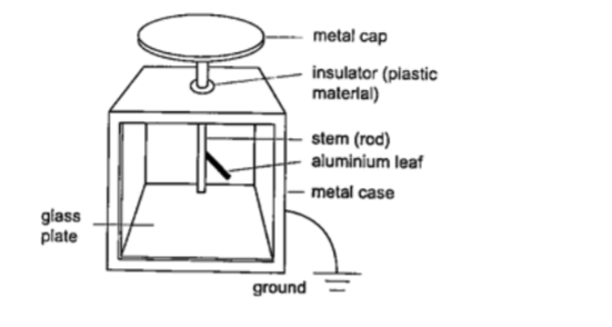
Other leaf electroscopes are made using gold strips and are referred to as gold leaf electroscope.Charging and discharging an electroscope
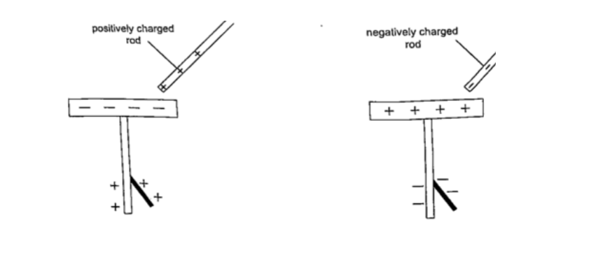
When a charged body is brought near the cap of the electroscope the leaf diverges, and when removed it collapses.
When a negatively charged body is brought near the metal cap electrons are repelled from the cap to the lower parts of the stem and the leaf.
This concentration of negative charges makes the leaf to diverge.
Similarly when a positively charged body comes near the metal cap the electrons are attracted by the protons and move up the stem, leaving a high concentration of positive charges which make the leaf to diverge.
If you touch the metal cap with your finger the leaf collapses showing that the charges have been discharged through your body.An uncharged body will always cause the leaf of a charged electroscope to collaps e regardless of the charge on the electroscope.
This shows that charge moves from the charged electroscope to the uncharged body.
Conductors and insulators
Conductors are those substances which allow easy passage of a charge. Insulators do not allow a charge to pass through easily .
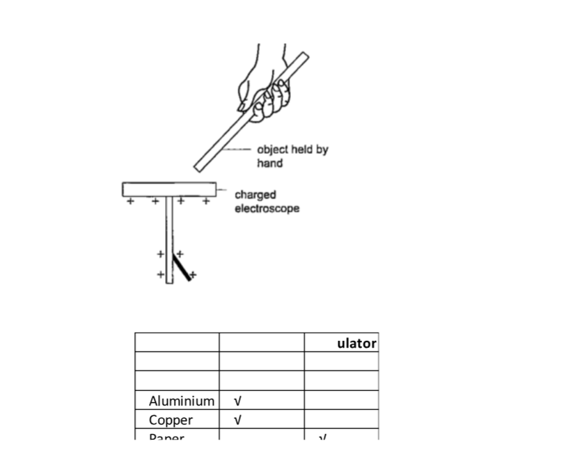
A charged electroscope can be used to classify objects into conductors and insulators.
Experiment: Arranging objects into conductors and insulators.
Procedure
1. Charge an electroscope by rubbing it with fur until its leaf diverges.
2. Obtain a number of materials like aluminium, paper, copper, iron, cloth, glass, wood etc.
3. Hold these items in your hand in turns and touch the charged electroscopes’ metal cap with it.
4. Record your results in the table shown below.
Charging an electroscope by inductionWe have seen that when a charged body is brought near a leaf electroscope, charges are transferred to the electroscope and the leaf diverges.
This method of transferring charge without actual contact is called induction.
Uses of the electroscope
1. To detect the presence of charge on a body.
2. To test the quantity of charge on a charge body.
3. To test for insulation properties of a material.
4. To test the sign of charge on a charged body.
Applications of electrostatic charges.
1. Electrostatic precipitator – they are used in chimneys to reduce pollution by attracting pollutants through electric ionization which then traps them by use of plates (wire mesh). Finger printing and photocopying uses the same principle.
2. Spray painting– as air cruises above the paint droplets acquire similar charges therefore spread out finely due to repulsion. Little paint is then used.
Dangers of electrostatics
As liquid flows through a pipe its molecules get charged due to rubbing against inner surface.
If the liquid is flammable then this can cause sparks and explode.
The same happens to fuels carried in plastic cans therefore it is advisable to carry fuel in metallic cans to leak out the continuously produced charges.
Chapter Ten
Cells and Simple Circuits.
Introduction
Work done per unit charge is called electrical potential. Current is the flow of charge.
For current to be continuous, potential difference between the two points must be sustained.
Sources of continuous currents.
In this process work is continuously done in moving electrons against a repulsive force. A device in which the potential difference is sustained is called a cell .
A cell is a source of continuous current.
The end of a cell with a higher potential (fewer electrons)is called the positive terminal while the end with lower potential (higher electrons) is called the negative terminal.
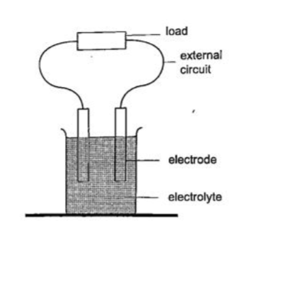
1. Chemical sources
A good example is the electrochemical cell where simultaneous oxidation-reduction process occurs between the electrolyte and the electrodes.
An external circuit is used to transfer the electrons.
Examples of electro chemical cells are the primary cells i.e. the dry cell and Daniel cell.
The reactants must be replaced after supplying a given amount of energy. The second type is the secondary cell or storage cell where the chemical reaction is reversible i.e. the lead-acid battery and nickel-cadmium cell.
The third type is the fuel cell where chemical energy supplied is continuously converted into electrical energy i.e. hydrogen-oxygen cell used in spacecraft.
2. Thermoelectric sourcesA good example is the thermocouple where p.d is sustained by the continuous heating which keeps the terminals at different temperatures.
3. Solar sources
This occurs when some semi-conductor material called P and N type absorbs light at their transition region and gain energy enough to move electrons just like in cells.
They are used in spaceships, calculators, lighting, etc.
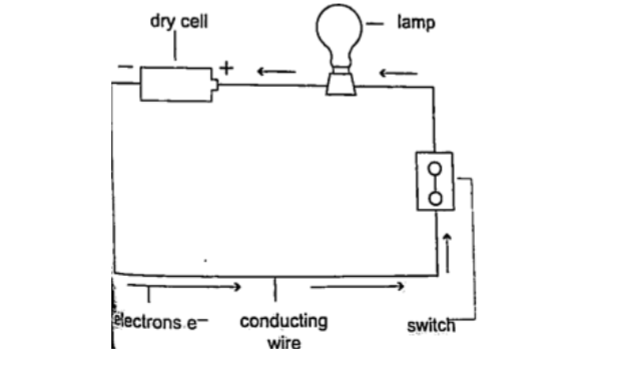
DC circuits
Conventionally current is a flow of positive charge and flows from the positive terminal to the negative terminal.
A dc current is the flow of current in one direction that is from the positive terminal to the negative terminal when the loop is closed.
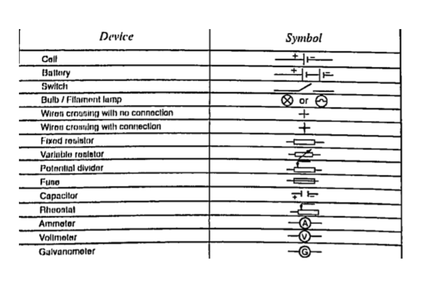
Circuit symbolsThe following symbols are used in electrical circuits.
Potential difference and currentPd is the work done by moving an electron from one point of a conductor to another. Current is by definition the rate of flow of charge.
Current = charge / time
The SI unit for current is the ampere, A.
1 A = 1 Coul/sec
1 milliampere (mA) = 10-3 A
1 microampere (µA) = 10-6 A
Examples
1. The current in a single loop is 3.0 A. How long would it take for a charge of 3600 coulombs to flow?
Solution Current = charge / time
Time = charge / current => 3600 / 3 = 1200 seconds = 20 minutes.
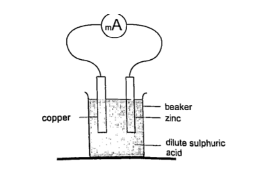
2.Primary cells
This is a cell formed by dipping two different metals into an electrolyte. Experiment: making a simple cell
Procedure
1. Take a piece of copper strip and zinc strip and clean thoroughly with emery paper.
2. Put the two strips in a beaker containing dilute sulphuric acid.
3. Observe what happens to the strips.
4. Connect the strips externally to a milliameter and a voltmeter.
DiscussionSulphuric acid is chemically written as, H2SO4 —–> 2H+ + SO42-
The electrons liberated by the acid move to the zinc electrode Zn ——> Zn2+ + 2e-
The hydrogen ions move to the copper strip
2H+ + 2e- —-> H2
Copper strip therefore becomes positively charged while the zinc becomes negatively charged electrode.
The accumulation of bubbles around the copper strip is called polarization.
The bubbles formed around the zinc strip is the reaction of acid with zinc impurities and is called local action.
Polarization produces insulation between the strip and the acid cutting off production of current eventually.
This is known as the internal resistance of the cell. Loc al action eats away the zinc strip and a mercury coat is applied to prevent this (amalgamation). Polarization and local action are the main defects of simple cells.
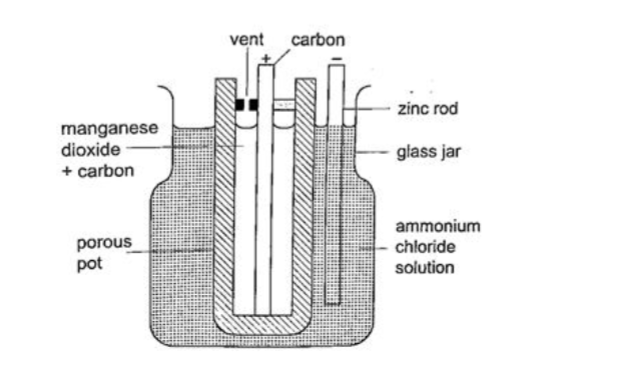
The Leclanche’ cell
In this cell carbon rod is used as the positive terminal and zinc as the negative electrode. The electrolyte is ammonium chloride solution (NH4Cl). No polarization since it is reduced by use of manganese (IV) oxide (MnO2) which oxidizes hydrogen into water. Local action still occurs. They are used in operating bells and telephone boxes.
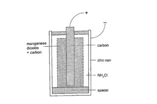
The dry cellIt is referred to as dry because it contains no liquid. The ammonium solution is replaced with ammonium chloride jelly or paste, the manganese (IV) oxide and carbon powder are used as the depolarizer.
The hydrogen gas produced is oxidized to water which eventually makes the cell wet after use. They are used in torches, radios calculators etc.
Secondary cellsThey are also called storage cells since they store electrical charge as chemical energy.
Experiment: To charge and discharge a simple secondary cell
Procedure
1. Set up the apparatus as shown below.
2. Close the switch S1 and observe the changes in the plates if any.
3. Note how the ammeter reading varies with time.
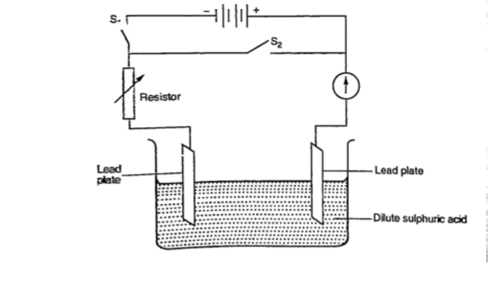
DiscussionWhen charging oxygen is produced at the anode and hydrogen at the cathode.
The oxygen reacts with lead to form lead (IV) oxide which is deposited at the anode.
The hydrogen formed has no effect.
When discharging current flows in opposite direction with oxygen be ing formed at the cathode and hydrogen at the anode.
The colour of the positive electrode changes from brown to grey.
Lead-acid accumulator.
A 12V accumulator has six cells connected in series. Each cell has several plates forming lattice grid with positive plates carrying lead (IV) oxide and the negative plates having spongy lead. They are placed close to one another with an insulating sheet separating them. They are rated in ampere-hours i.e. 30 Ah means that it can supply 1 ampere for 30 hours or 2 amperes for 15 hours etc.
Example
A battery is rated at 30 Ah. For how long will it work if it steadily supplies a current of 3 A?
Solution
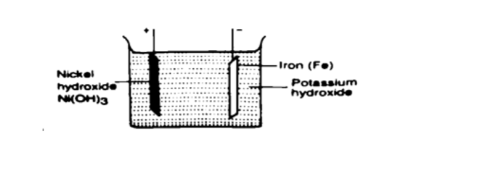
Q = I t, hence t = Q / I => 30 / 3 = 10 hours. Alkaline accumulators
Potassium hydroxide (KOH).Nickel hydr oxide (Ni (OH) forms the positive electrode while iron forms the negative electrode.
They are two types nickel cadmium (NiCd) and nickel iron (NiFe).
They are used in ships, hospitals and buildings where large currents are required for emergencies.
Advantages of alkaline accumulators over lead-acid accumulators1. Large currents can be drawn from them
2. They require little maintenance
3. They are portable
4. They can remain discharged for a long time without getting ruined.
Disadvantages
1. They are very expensive
2. They have lower e.m.f per cell.physics
Physics Notes Form 2
Physics Form Two Notes
Chapter One
Magnetism
Introduction
Magnets are substances that are able to attract and hold items. Lodestone is the only known natural magnet which was discovered by the Chinese 2,000 years ago.
Other magnets produced artificially by man are called artificia l magnets.
Magnets and non-magnetic materials
Magnetic materials are those that are strongly attracted by magnets while non-magnetic ones are those that are not affected by magnets.
Iron, steel, cobalt and nickel are magnetic substances, while wood, glass and copper are examples of non-magnetic substances.
Substances that are repelled by magnets are said to be diamagnetic whereas those which are strongly attracted i.e. iron, nickel, cobalt are called ferromagnetic materials .
The materials that are so lightly attracted such that the magnet seems to have no effect on them are called paramagnetic materials (mostly non-magnetic materials).
Ferrites are a mixture of iron oxide and barium oxide are the most newly developed magnetic materials.
Ceramic magnets or magnadur magnets are made from ferrites and are very strong.
Properties of magnets
1. They are double poled substances with both the North and South poles.
2. Like poles repel and unlike poles attract. Repulsion is a sure method of determining whether two substances are magnets.
3. The greatest magnetic force is concentrated around the poles of a magnet.
Magnetic field patterns.
Magnetic field is the space around a magnet where magnetic field (force) is observed.
Plotting field patterns
A line of force gives the direction of the magnetic field at each point along it.
Their closeness is a measure of the strength of the magnetic field or of the force that would be exerted by the bar magnet.
Examples of field patterns.
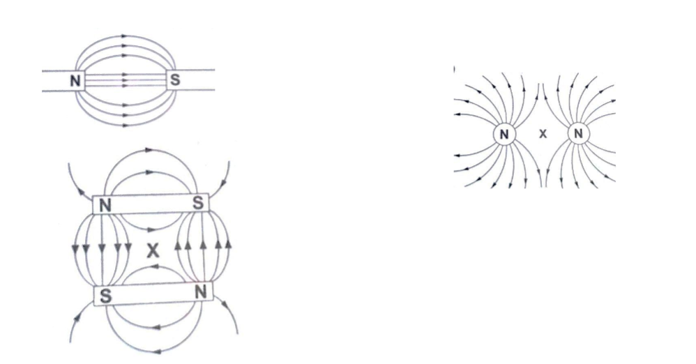
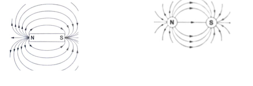
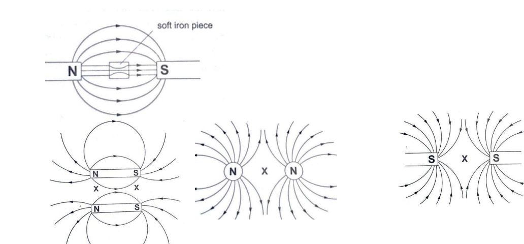
The points marked ‘X’ are called neutral points where there is no magnetic field at such points.Watches (non-digital), electron beams in cathode ray tubes and TV sets are shielded from external magnetic fields by placing a soft-iron cylinder around the neck of the tube or watch.
Making magnets
The following are methods used to make magnets.
a) Magnetic induction – this is a process by which magnets are made by placing ferromagnetic materials in a magnetic field. Materials like iron lose their magnetism easily and are said to be soft while others like steel gain magnetism slowly but retain it longer and are therefore said to be hard and are used to make permanent magnets.
b) Magnetizing by stroking – the object to be magnetized is placed on a bench then a bar magnet is dragged along the length of the bar from one end to the other.
This is repeated several times and the object becomes magnetized. This method is known as single-stroke method.
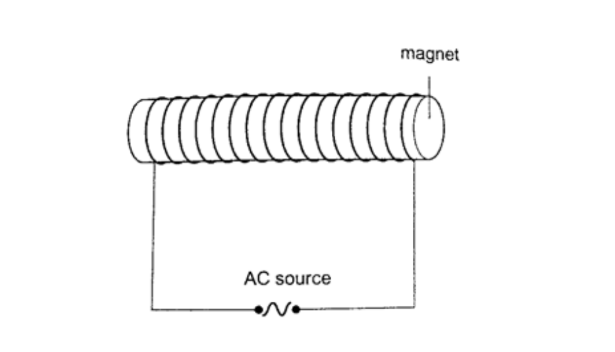
c) Magnetizing using an electric current – this is the use of magnetic effect of an electric current through a solenoid (insulated wire of many turns).
DemagnetizingDemagnetizing is the process of removing magnetic properties of a magnet .
The following methods are which a magnet can lose its magnetism;
a) Hammering them hard with their poles facing E-W direction
b) Heating them strongly
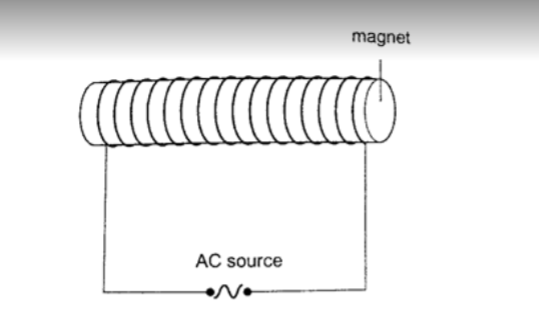
c) Placing a magnet inside a solenoid and passing an a.c. current through it for a short time.
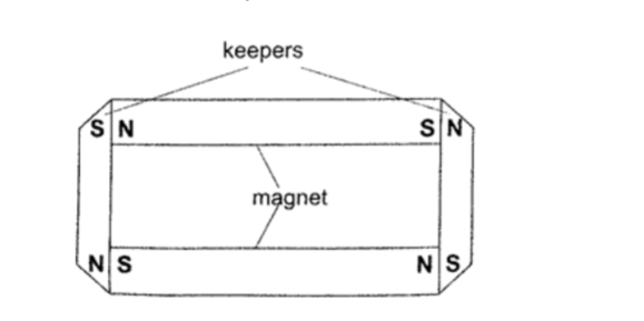
Caring for magnetsa) Magnets should be stored in pairs with unlike poles adjacent to each other attached to pieces of soft iron called keepers.
b) Magnets should not be hammered especially with their poles facing E-W direction.c) Magnets should not be heated strongly or dropped roughly on hard surfaces.
d) Magnets should not be placed near alternating currents.
e) Magnets should be kept dry and clean since rust can make them lose their magnetism.
Uses of magnets
1. Used in making other magnets
2. Used in making loud speakers
3. Used in making moving coil meters
4. Used in making telephone speakers.
Domain theory of magnetism.
In ferromagnetic substances small atomic magnets form large groups called domains.
These atomic magnets face one direction where the direction varies from one domain to another.
In an un-magnetized crystal the directions of these domains are different hence their resultant magnetism is zero.
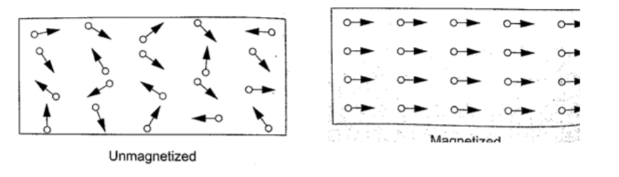
When a magnetic material is placed in a magnetic field the atomic magnets rotate and eventually all domains face the same direction.When this happens then the material becomes magnetized.
When a material is magnetized we say it is saturated.
This means that the magnetism of the material cannot be increased by any other method and this is the domain theory of magnetism.
Chapter Two
Measurement II
Measuring length using vernier callipers.
Vernier callipers is used when higher accuracy in measurement is required and this cannot be done using a metre rule.
Vernier callipers has two scales; main scale and vernier scale. Outside jaws are used to measure both lengths and external diameters, inside jaws for measuring internal diameters while the tail is used for measuring depths of cavities .
The main scale is divided into cm and mm. The vernier scale is divided into 10 equal divisions of 0.9 mm each. The accuracy of vernier callipers is 0.10 mm.

The reading is taken in two steps;a) The main scale is read at zero mark of the vernier scale. The values given in cm.
b) The vernier is read at the position where a mark on the vernier scale is exactly lined up with a mark on the main scale. The values are given as a two decimal of a cm.
Examples
1. Give the reading in the following diagram.
SolutionMain scale reading: – 2.7 cm
Vernier scale reading: – 0.04 cm
Adding both we get 2.74 cm.
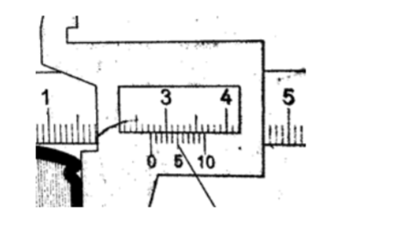
2. What is the reading of the vernier callipers shown below?
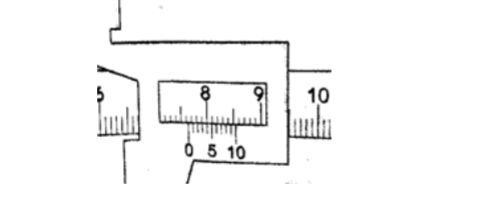
SolutionMain scale reading – 7.6 cm Vernier scale reading – 0.04 cm Adding both readings we get 7.64 cm.
Micrometer screw gauge
It is a device used to measure small lengths.
It has an accuracy of 0.01 mm. It has two scales; the sleeve scale and thimble scale.
The sleeve scale is divided into upper and lower scales with the upper division in mm and lower divisions in 0.5 mm.
Thimble scale is divided into 50 equal divisions each division consisting of 0.01 mm.

The reading is taken in two steps;a) The reading on the sleeve scale is read ta the point where it touches the edge of the thimble in mm and half mm.
b) The thimble scale is read at the point where the centre line of the sleeve is parallel to the thimble scale division.
Examples
1. Give the reading in the following.
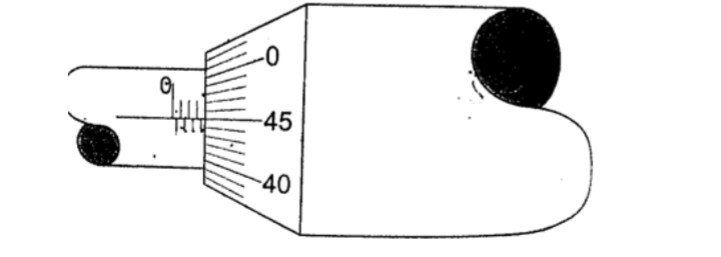
Solution Sleeve reading – 3.5 mm Thimble reading – 0.45 mm Adding up we get 3.95 mm.2. What is the reading in the following micrometer screw gauge?
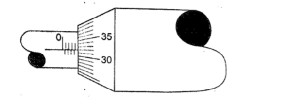
SolutionSleeve scale reading – 4.0 mm Thimble scale reading – 0. 32 mm Adding up the two we get 4.32 mm.
Calculating the size of a molecule.
Both the volume and area of a drop can be calculated using the following formulas Volume = 4/3 πr3 and Area = πr2h.
Examples
1. A drop of olive oil, whose volume is 0.12 mm 3, was placed on a surface of clean water.
The oil spread and formed a patch of area 6.0 × 104 mm2. Estimate the size of the olive oil.
Solution
Volume = 0.12 mm2. Area of the oil patch = 6.0 × 104 mm2. Volume = area × thickness of the patch, therefore Thickness of the oil patch = volume / area = 0.12 / 6.0 × 104 = 2.0 × 10⁻⁶ mm or 2.0 × 10⁻⁹ m.
2. Suppose an oil drop has a volume of 0.10 mm 3 and forms a film with a radius of 10 cm.
Calculate, the thickness of the oil film. Solution
Area of the film = πr2 = 3.14 × 10 × 10 = 314 cm2 = 31,400 mm2.
Thickness of the oil film = volume / area, hence 0.10 / 31,400 = 3.0 × 10⁻⁶ mm.
(The thickness of the oil film is called upper limit to the size of molecule because the molecule cannot be bigger than the thickness of the oil film)
Chapter Three
Turning Effect of a Force
Turning effects
The turning effect of a body is called the moment of that force.
The turning effect produced depends on both the size of the force and the distance from the pivot.
The moment of a force about a point is the product of the force applied and the perpendicular distance from the pivot (or turning point) to the line of action of the force.
Hence, Moments of a force = Force × perpendicular distance from pivot.
The law of moments
The law of moments states that “when a body is in balance or in equilibrium, the sum of the clockwise moments equals the sum of anti-clockwise moments”.
The SI units of the moments of a force is Newton metre (Nm).
Examples
1. A uniform rod of negligible mass balances when a weight of 3 N is at A, weight of 3 N is at B and a weight of W is at C. What is the value of weight W?
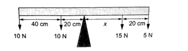
2. The following bar is of negligible weight. Determine the value of ‘ x’ if the bar is balanced.Solution
The distance from the turning point to the line of action can be determined as,
Clockwise moments = 10 × 30 = 300 N cm, Anticlockwise moments = 10 × ‘x’ = 10 x. N cm. Using the principle of momentsAnti-clockwise moments = clockwise moments
10 x = 300, hence x = 30 cm.
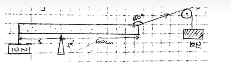
3. Study the diagram below and determine the value of X and hence the length of the bar.
SolutionClockwise moments = 15x N + 5(X × 20) N
Anticlockwise moments = (20 × 10) + (60 × 10) N cm, = 800 N cm.
Anti-clockwise moments = clockwise moments
800 N cm = 15X + 5X + 100
800 n cm = 20X + 100
20X = 700
X = 35 cm.
Therefore, the length of the bar = 40 + 20 + 35 + 20 = 115 cm.
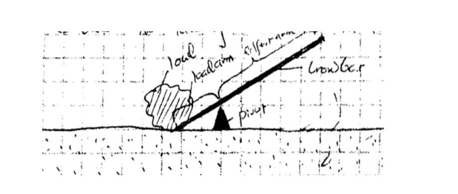
The lever
A lever is any device which can turn about a pivot or fulcrum .
The applied force is called the effort and is used to overcome the resisting force called the load. We use the law of moments in the operation of levers.
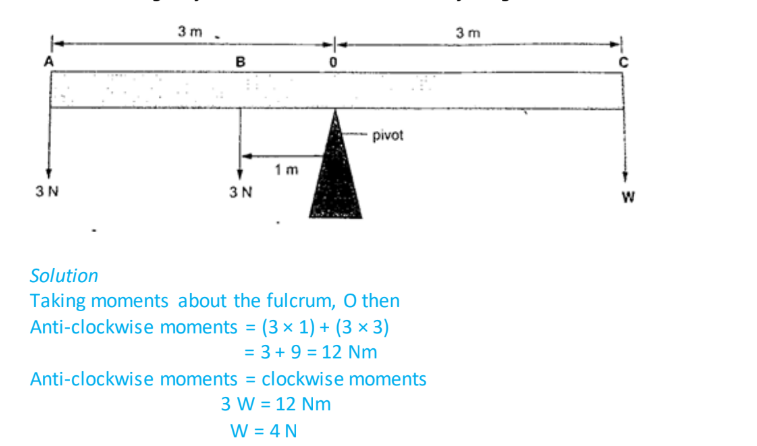
ExampleConsider the following diagram. (The bar is of negligible mass). Determine the effort applied.
Solution
Taking moments about O. Then, clockwise moments = effort × 200 cm. Anticlockwise moments = 200 × 30 cm.
Effort = (200 × 30)/ 200 = 30 N.
Chapter Four
Equilibrium and Centre of Gravity.
Centre of gravity
Centre of gravity or C.G is the point of balance of a body in which the total weight of the body seems to act through.
For regular shaped bodies the C.G is at the geometric centre of the body. For irregular bodies their weight still acts at the centre of the gravity and the law of moments can be used to determine the weight of the body.
Example
The figure below shows a uniform bar of weight ‘W’ and length 80 cm. If a force of 20 N keeps it in balance, determine the weight ‘W’ of the bar.
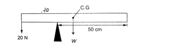
SolutionTaking moments about the pivot, clockwise moments = W × 20 N cm.
Anticlockwise moments = 20 × 30 N cm. Clockwise moments = anticlockwise moments 20 W = 600, therefore W = 30 N.
Parallel forces and equilibrium
For a body to be in equilibrium (neither moving nor rotating), under the action of parallel forces, the following conditions will be satisfied;
a) The sum of upward forces must be equal to the sum of downward forces.
b) The sum of clockwise moments equals the sum of anticlockwise moments.
The two are called the first and second condition of equilibrium respectively.
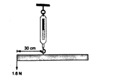
Examples 1. A uniform rod of length 1.0 m is hung from a spring balance as shown and balanced in horizontal position by a force of 1.6 N. Determine; a) The weight of the rod
b) Reading of the spring balance.
Solution
a) Let the weight of the rod be ‘W’. W acts at 50 cm mark, therefore taking moments about point of suspension, clockwise moments = W × 0.2 Nm = 0.2W Nm.
Anticlockwise moments = 1.6 × 0.3 = 0.48 Nm.
Using the law of moments, then
Anticlockwise moments = clockwise moments
0.48 = 0.2 W, hence W = 2.4 N
b) Upward forces = downward forces
Downward force = W + 1.6 N
= 2.4 + 1.6
= 4.0 N
Upward force = reading of the spring balance = 4.0 N
2. A uniform rod is 1.0 m long weighs 5 N. It is supported horizontally at one end by a spring and the other end rests on a table as shown below. A mass of 2kg is hung from the rod as shown; determine,
a) Reading of the spring balance
b) Reaction force, F, from the table.
Solutiona) The 2kg mass and the weight of the rod (5 N) gives clockwise moment while the spring balance provides anticlockwise moments.
Clockwise moments = (2 × 10) × 0.4 + (5 × 0.5) = 10.5 Nm. Anticlockwise moments = S × 1 (reading of the spring balance)
1S = 10.5, hence S = 10.5 N. b) Upward forces = downward forces
Downward forces = (2 × 10) + 5 = 25 N Therefore F+ 10.5 = 25, hence F = 14.5 N.
Stability
This is a term which explains how easy or difficult it is for an object to topple over when a force is applied to it. Factors affecting stability,
a) Base area – the bigger the base area the more the stability.
b) Position of the centre of gravity – the higher the centre of gravity the less stable the body will be.
States of equilibrium
1. Stable equilibrium – if a body is displaced by a small amount of force it returns to its original position.
2. Unstable equilibrium – if a body is displaced by a small amount of force it toppled over and does not return to its original position.
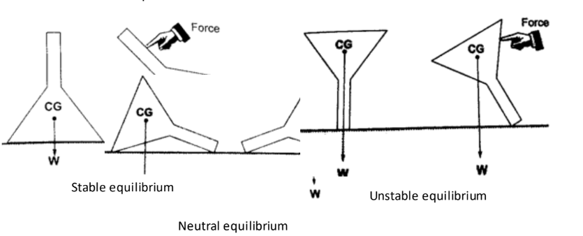
3. Neutral equilibrium – a body is at rest in whichever position it is placed in i.e. it does not rise or fall when displaced.Applications of stability
Neutral equilibrium It is used mainly in the design of motor vehicles i.e.
a) Racing cars – they have a low and wide wheelbase to increase their base area.
b) Double decker buses – they are manufactured with a low centre of gravity by mounting their chassis and engines as low as possible.
Chapter Five
Reflection at Curved Surfaces
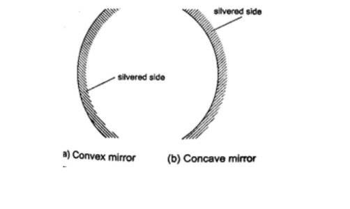
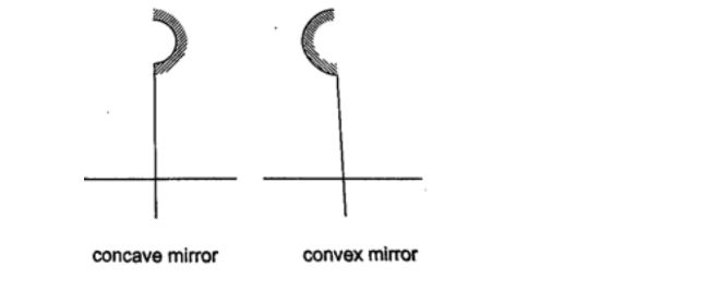
Concave and convex mirrors
They are also known as spherical mirrors and are formed when a spherical glass is silvered .
If the inside is silvered a convex or diverging is formed while a concave or converging mirror is formed when the outside is silvered.
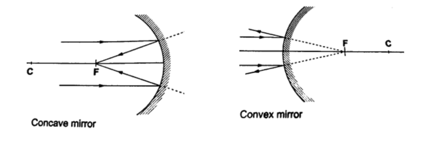
Parts of a spherical mirror.1. Centre of curvature (C) – this is the centre of the sphere of which the mirror is part of. The centre itself is called the pole (P).
2. Principal axis – this is the line joining the centre of curvature (C) to the pole (P).3. Principal focus (F) – is a point on the principal axis through which a ray is reflected when it hits a concave mirror.
In a convex mirror the ray is reflected and appears to originate from the point. F is virtual for a convex mirror while it is real for a concave mirror.
4. Radius of curvature (r) – this is the distance from the pole to the centre of curvature. The distance from the pole to the principal focus is called the focal length (f).
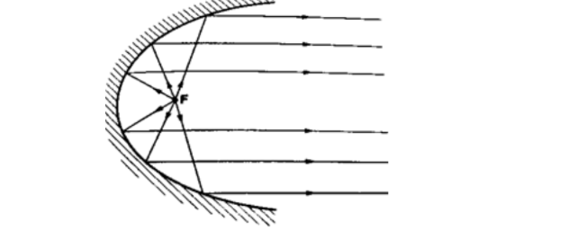
Parabolic mirrors.They produce a wide parallel beam or converge a large beam of light to a point. They are widely used in making car headlights or in spotlights.
Images formed by spherical mirrors.Location of images using ray diagrams.
When drawing ray diagrams the following symbols are used to represent the mirrors.
The image is located by drawing any two of the following rays:i) A ray parallel to the principal axis which is reflected through the principal focus.
ii) A ray through the centre of curvature which is reflected along its own path since it hits the mirror normally.
iii) A ray through the principal focus which is reflected parallel to the principal axis.
Virtual images are formed when rays diverge and as such the rays are extended backwards using dotted line till they meet.
The image formed is also dotted since it is not formed by an intersection of real rays.
A real image is formed by intersection of real rays.
Concave mirror.
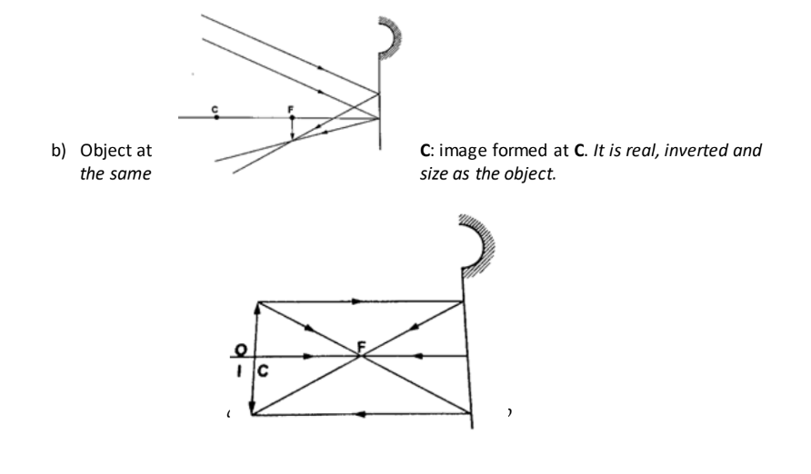
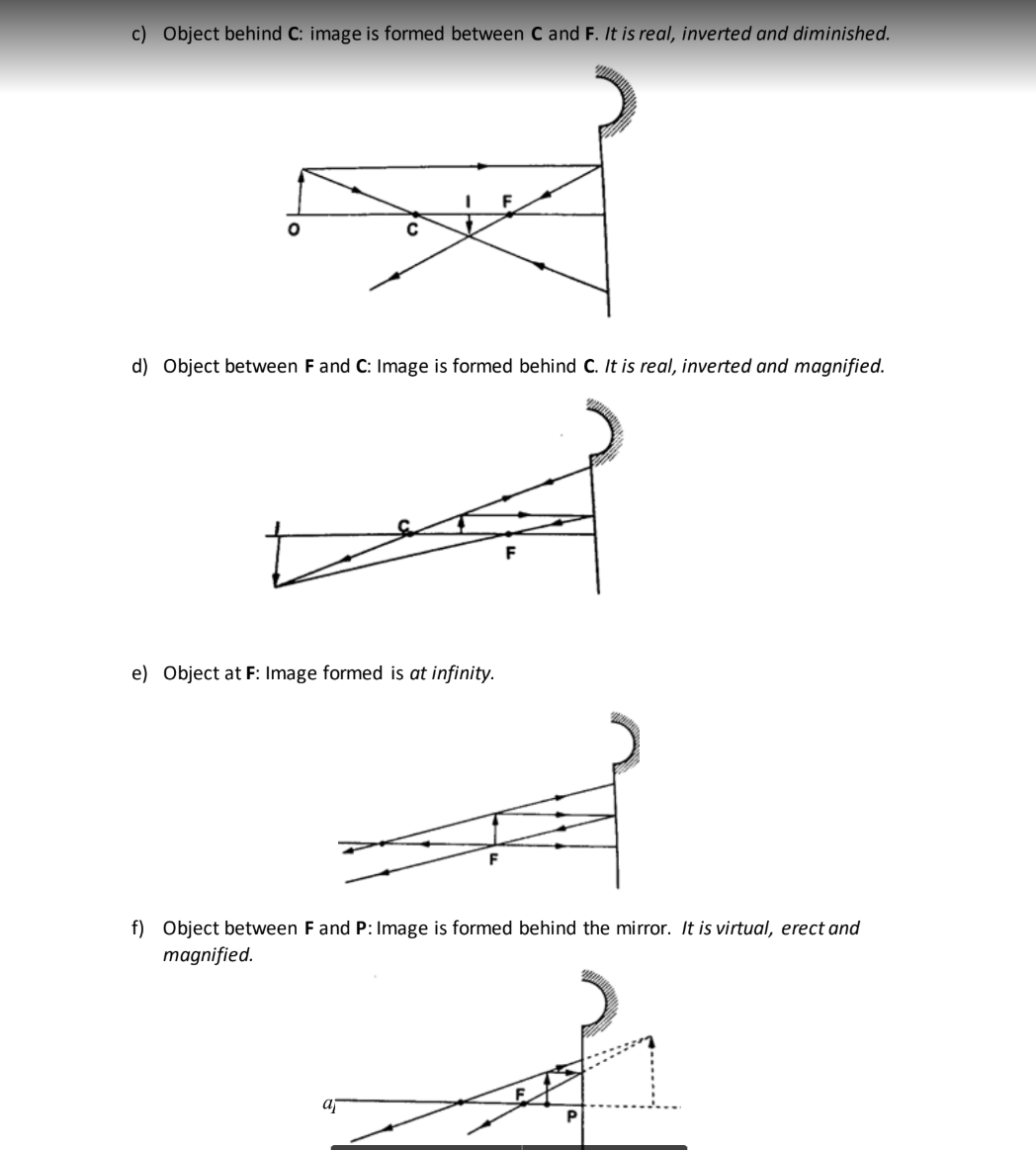
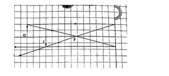
a) Object at infinity: image is formed at F. It is real, inverted and diminished.
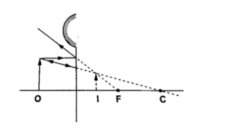
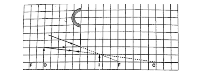
Convex mirror.g) Image is always formed behind the mirror. It is virtual, erect and always diminished.
Applications of curved reflectors.a) They are used in satellite dishes.
b) They are used in making shaving mirrors.
c) They are used in telescopes.
d) They are used in driving mirrors.
Magnification.
Magnification is the ratio of the image size to the object size.
Magnification (M) = height of the image / height of the object.
When the ratio is greater than one we say the image is magnified and when less than one we say it is diminished.
Also magnification = image distance from the mirror / object distance from the mirror.
Examples
1. Determine the size, position and nature of the image of an object 5.0 cm tall, placed on the principal axis of a concave mirror of focal length 15 cm, at a distance 35 cm from the mirror.
Solution
Let 1 cm represent 5 cm. Then the focal length is 3 cm.
Object distance = 7 cm, object height = 1 cm.
From the scale drawing,Image position = 5.4 cm × 5 = 27 cm in front of the mirror.
Image size = 0.75 cm × 5 = 3.75 cm. Image is real and inverted.
2. A vertical object 5 cm high is placed 10 cm in front of a convex mirror of focal length 15 cm.
find the position, size and nature of image formed. Determine the magnification of the image.
Solution
Let 1 cm represent 5 cm, then the focal length = 3 cm, object size = 1 cm Object distance = 2 cm.
From the scale drawing,Image position = 1.2 cm × 5 = 6.0 cm behind the mirror. Image size = 0.6 cm × 5 = 3.0 cm.
The image is virtual and erect.
Magnification = image dist. / object dist. Hence 6 /10 = 0.6 (diminished).
Chapter Six
Magnetic Effect of an Electric Current.
Introduction: Oersted’s discovery.
Hans Christian Oersted discovered the magnetic effect of a current in 1819. The direction of the field is dependent on the direction of the current.
This discovery brought about the development of electric bells, electric motors, telephone receivers and radios.
Determining the direction of the lines of force.
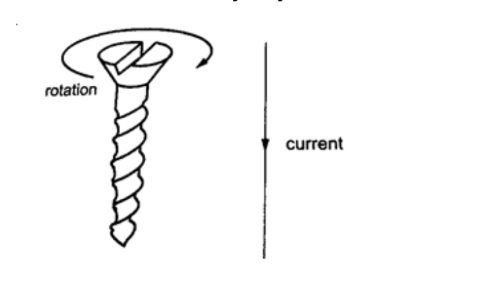
The direction of the lines of force can be determined using a simple rule called the right-hand screw rule.
This rule states that “if a right-hand screw advances in the direction of the current , then the rotation of the screw is in the direction of the field”.
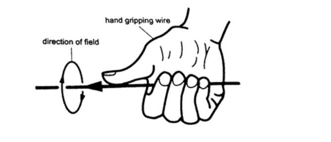
Another rule is the right-hand grip rule which states that “if the wire carrying a current is gripped with the right hand, using the thumb along the conductor and pointing in the direction of the current, then the direction of curled fingers is in the direction of the lines of force”.
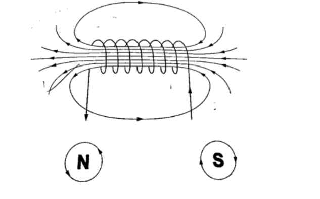
Magnetic field due to a solenoid. The rule for polarity.A solenoid is a cylindrical coil of wire acting as a magnet when carrying electric current.
The direction of the field can be determined using a simple rule stated as follows “if the coil (solenoid) is viewed from one end and the current flows in an anticlockwise direction at that end, then that end is the North Pole.
If the current flows in a clockwise direction, then that end is the South Pole”.
Electromagnets.An electromagnet is a soft metal core made into a magnet by passing an electric current through a coil surrounding it .
They only maintain their magnetism if current continues to flow, if switched off they lose their magnetism.
Factors affecting the strength of an electromagnet.
1. Increasing current through the coil.
2. Increasing the number of turns of the coil.
3. Using iron of C- core shape which brings both magnetic poles together.
Some applications of electromagnets.
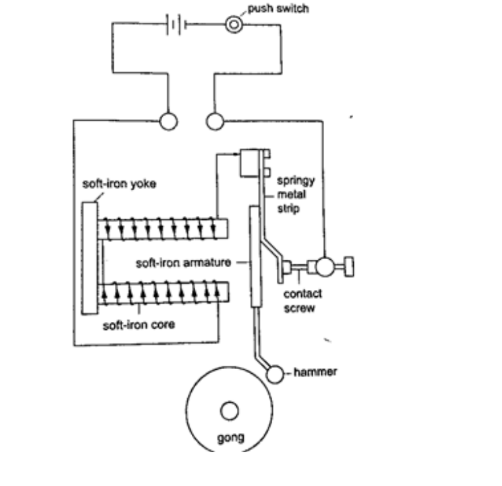
a) Electric bell
When the switch is closed the current passing through the solenoids magnetizes them and they pull the soft iron armature which makes the hammer hit the gong therefore producing sound. When the hammer hits the gong the contact between the spring and the screw is broken and then stops the current from flowing.
The soft iron core loses its magnetism and releases the armature which is then pulled back by the screw.
The contact between the spring and the screw is regained and the process repeats itself again and again therefore the gong is struck continuously.
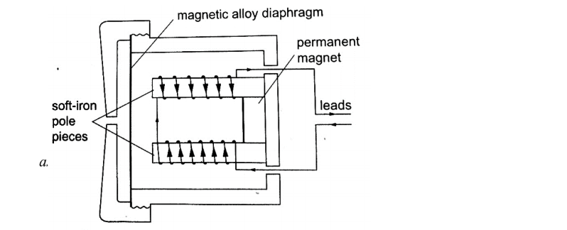
b) Telephone receiver.It consists of a u-magnet made by attaching two soft-iron bars to the end of a short permanent magnet.
The solenoids are wound in opposite directions around the bars. When the phone is lifted the current flows through the solenoids depending on the microphone on the other end of the line.
These varying current spasms induce magnetism of varying strengths in the iron bars which in turn causes the magnetic alloy diaphragm to vibrate differently producing sound.
Force on a current-carrying conductor in a magnetic field.When a conductor carries a current in a magnetic field a force acts on it.
The direction of the force depends on the directions of the field and current.
The factors affecting the magnitude of the force are;
a) The current flowing in the conductor
b) The strength of the magnet
c) The length of the conductor in the magnetic field.
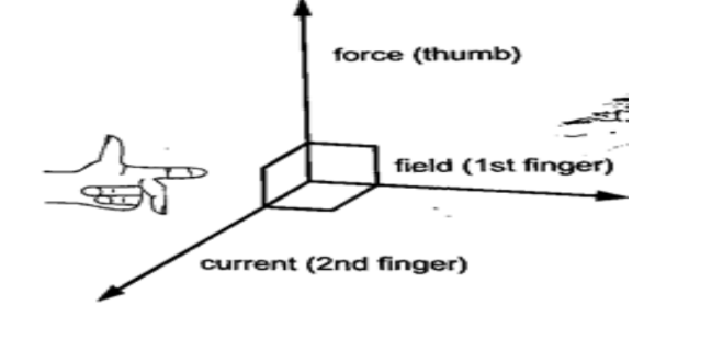
The relationship between the directions of the current, field and force are mutually perpendicular.
They are summarized in a law called Fleming’s right-hand rule or the motor rule.
This rule states that “if you hold the first finger, the second finger and the thumb of your left hand mutually perpendicular to each other, so that the first finger points in the direction of the magnetic field and the second finger points in the direction of the current in the conductor, then the thumb points in the direction of the force acting on the conductor”.
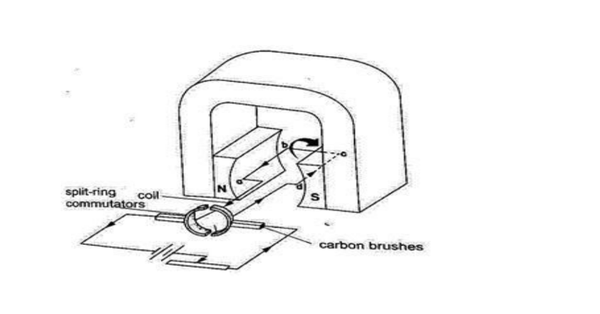
Applications of the force on a conductor.Simple D.C motor.
Consists of a rectangular coil of wire mounted on an axle which can rotate between the poles of a magnet.
For the rotation to be continuous the ends of the coil is connected to half -rings called the split-ring commutators.
The battery terminals are attached to brushes which slide on these half-rings. D.C motors are useful as car starter motors, hand drills, machine motors, fans etc.
Chapter SevenHooke’s Law.
Hooke’s law states that “the extension of a spring is proportional to the applied force, provided that the force is not large enough to deform the spring permanently”.
Mathematically expressed as Force α extension.
Spring constant
Since Force α extension then Force / Extension = constant (k). The constant of proportionality (k) is called the spring constant. F / e = k or Force (N) = k e. The spring constant is a measure of the stiffness of a spring.
The greater the constant the stiffer the spring.
The spring constant varies with the following;-
a) Material – identical springs mad of different materials will have different constants i.e.steel and copper.
b) Diameter – the stiffness decreases with the increase in diameter.
c) Thickness of the wire – a spring made of a thicker wire is stiffer than the one made of thin wire of the same material.
d) Length of spring – a short spring is stiffer than a longer one.
e) Number of turns per unit length – a spring with higher number of turns per unit length is less stiff than the one with fewer turns per unit length.
Example
1. If the springs shown below are similar and the constant of proportionality (k) is 100 Nm-1, determine total extension in each arrangement.
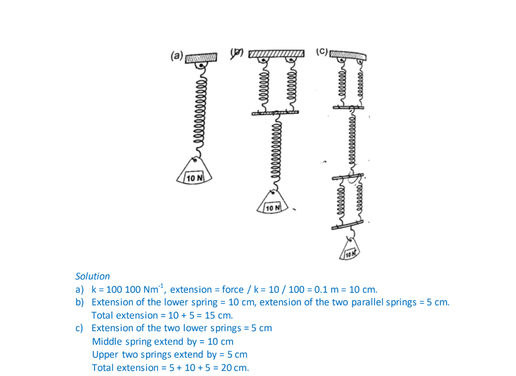
The spring balanceIt is made up of a spring mounted in a metal or plastic casing.
The spring is fitted with a pointer which moves along a calibrated scale divided into ten equal parts.
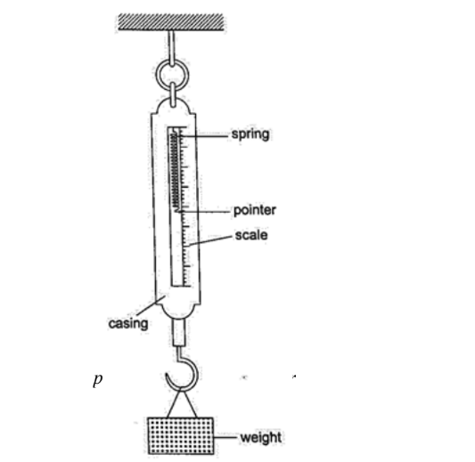
Examples1. A load of 4 N causes a certain copper wire to extend by 1.0 mm. Find the load that will cause a 3.2 mm extension on the same wire. (Assume Hooke’s law is obeyed).
Solution
F α e also F1 / F2 = e1 / e2 = F2 = (4 × 3.2) / 1.0 = 12.8 N. 2. A body of 200 g was hung from the lower end of a spring which obeys Hooke’s law. Given that the spring extended by 100 mm, what is the spring constant for this spring? Solution F = α e, F = k e. F = 200 × 10-3 kg × 10 N /kg = 2 N. Extension = 100 × 103 m = 0.1 m.
Spring constant (k) = 2 / 0.1 = 20 N/m.
3. Two identical springs, whose spring constant is 6.0 N/cm, are used to support a load of 60 N as shown below. Determine the extension of each spring.
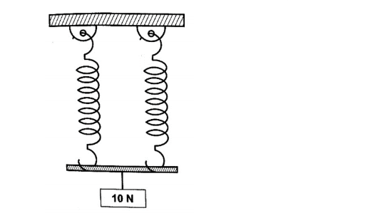
SolutionSince the springs are parallel their spring constant equals 2k. Therefore extension = Force / k = 2 F / k = 60 / 2 × 6 = 5 cm. Each spring will extend by 5 cm.
Chapter Eight
Waves I
A wave is simply a disturbance that moves through a medium . Other waves do not require a medium to travel i.e. they can travel in a vacuum, are known as electromagnetic waves e.g. radio, X-rays, gamma rays UV rays etc. Other waves require a material medium to be transferred and are called mechanical waves i.e. water, sound waves etc.
Transverse and longitudinal pulses and waves.
1. Transverse waves – they consist of a crest and a trough. In this case the displacement of the medium caused by these pulses are perpendicular to the direction in which the wave (disturbance) travels.
A pulse is a single non-repeated disturbance.
If the pulses are repeated periodically (regularly) they produce a series of waves called periodic transverse wave train.
They can be produced as shown below. Examples are water waves, light and radio waves.
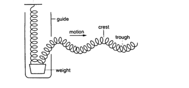
2. Longitudinal waves – these are waves whereby the particles of the medium vibrate parallel to the direction of movement of the disturbance .When several turns of a spring are pulled together (compression) and then released they tend to spread out to their original position.
When pulled apart (rarefaction) they also turn to their original position.
In this case the displacement of the spring is parallel to the motion of the wave and this is known as longitudinal. Examples are the sound waves.
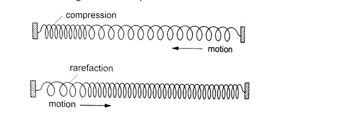
Characteristics of waves1. All waves have speed which depends on the nature of disturbance.
2. All waves have wavelength (distance between two successive points in a wave ).
Represented by the symbol λ and is measured in metres. 3. All waves have frequency ‘f’ which is the number of waves passing a point in one second. It is measured in cycles per second or hertz (Hz). The period of a wave is the time required for a complete wave to pass a given point.
Therefore T = 1 / f or f = 1 / T (period is measured in seconds).
The speed ‘v’ is given as; v = λ / T, since f = 1 / T then v = (1 / T) × λ = f λ or v = f λ. This is the wave equation.
4. All waves have amplitude which is the maximum displacement of the particles of the medium as the wave passes.
Examples
1. A rope is displaced at a frequency of 3 Hz. If the distance between two successive crests of the wave train is 0.8 m, calculate the speed of the waves along the rope.
Solution
v = f λ = 3 × 0.8 = 2.4 m Hz = 2.4 m/s.
2. The figure below illustrates part of the displacement-time graph of a wave travelling across water at a particular place with a velocity of 2 ms-1. Calculate the wave’s;
a) Amplitude
b) Frequency (f)
c) Wavelength (λ)
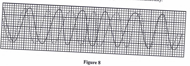
Solutiona) From the graph, maximum displacement (a) = 0.4 cm
b) From the graph, period T = time for one cycle = 0.20 seconds
So f = 1 / T = 1 / 0.20 = 5 Hz.
c) Velocity = f λ hence λ = 2 / 5 = 0.4 m.
Chapter Nine
Sound.
Sound is an important example of a longitudinal wave which is composed of both compressions and rarefactions. The frequency range in which compressional disturbances occur is called the sonic spectrum and is very large.
Sound is a range of compressional wave frequencies sensitive to human ear and is known as audio range which ranges from 20 Hz to 20,000 Hz.
Compressional waves with frequencies above and below the audio range are called ultrasonic and infrasonic frequencies respectively.
Nature and transmission of sound waves.
Sound waves require a material medium for transmission from one point to another. Sound waves therefore cannot be transmitted in a vacuum.
The rate of transmission diminishes as you move from solids, to liquids then to gases.
Characteristics of sound waves
1. Intensity and loudness – intensity of sound refers to the rate of flow of energy through an area.
The loudness of a sound generally varies with the intensity of sound.
The frequency of sound waves determines their intensity while the amplitude determines their loudness.
2. Frequency and pitch – pitch refers to the sharpness of a sound and is determined by its frequency.
3. Fundamental tones and harmonics – fundamental frequency is the vibration in a wire which has the lowest possible frequency.
The fundamental frequency and the tones with the frequencies that are whole multiples of the fundamental are called harmonics.
The fundamental frequency is also the first harmonic.
The number of segments vibrating in a string depends on the point at which the string is plucked.
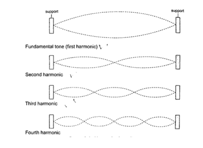
4. Quality of sound or timbre – quality of sound can be improved by adding the second harmonic to the fundamental frequency hence the quality depends on the number of harmonics produced simultaneously and their relative intensities.
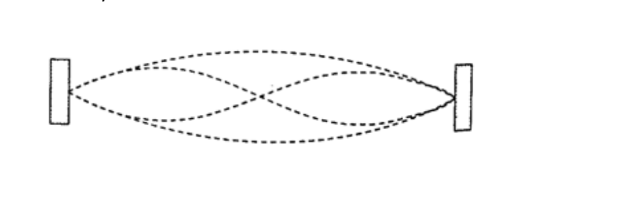
EchoEchoes are produced by reflection of sound waves from hard surfaces such as a wall or a cliff.
To hear an echo, the sound waves travels double the distance between the source and the reflector. So to determine the velocity of sound ‘v’ between two successive claps is given as v = distance from the reflecting surface / half the time taken between two successive claps Hence; speed ‘v’= distance / time = m/s.
Example
A boy strikes a railway line (steel) with a hammer.
If the speed of sound in steel is 5,200 m/s, determine the time taken for the sound to reach another boy 2.3 km down the railway line with his ear on the rail.
Solution
Time taken = distance / speed = 2300 / 5200 = 0.44 seconds.
Factors affecting the speed of sound
a) Temperature – speed increases with increase in temperature especially gases since the change in liquids and solids is small it can be neglected.
b) Nature of transmitting medium – different substances transmit sound waves at various speeds as shown below
(i) Air – 346 m/s
(ii) Hydrogen – 1339 m/s
(iii) Water – 1498 m/s
(iv) Aluminium – 5,000 m/s
(v) Iron – 5,200 m/s
(vi) Glass – 4,540 m/s
Example
A girl claps her hands once at a distance 250 m from a vertical cliff.
If the temperature in the surrounding is 50oC, how long does it take for her to hear the echo?
Solution
Distance travelled = 250 × 2 = 500 m
Speed of sound = (331.5 m/s at 00) the speed in air increases at about 0.6 m/s per 0C.
Therefore speed at 50oC = 331.5 + (0.6 × 5) = 334.5 m/s
Time taken = distance / speed = 500 / 334.5 = 1.5 seconds.
Chapter Ten
Fluid Flow
Fluid in physics refers to liquids and gases.
- To study fluid flow we have to make the following assumptions:1. We consider fluids to be incompressible
2. We assume that they have little or no internal friction or viscosity.
Streamline and turbulent flow.
The path followed by a small element of a moving fluid is called a line of flow . A streamline is a curve whose tangent at any point is in the direction of the fluid velocity at that point.
A streamline flow occurs when all elements of a fluid passing a particular point follow the same path or line of flow as the elements that passed through that point previously.
A streamline flow is achieved only when the speed is low.
If the speed increases it is characterized by whirls and eddies then it becomes a turbulent flow. Turbulent flow generally occurs when the speed is high and where there are sharp bends along the path of the fluid.
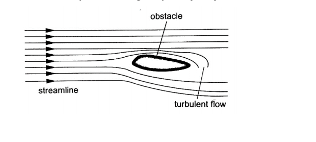
Equation of continuityConsider a fluid flowing (streamline flow) through a horizontal pipe with different cross – sectional areas as shown.
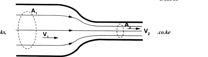
Let the cross -sectional area in both sections be A1 and A2 and the corresponding speeds of the fluid be V1 and V1 respectively.The volume of fluid flowing per second in each section is given by; V = A L = A v t = A v. Where L, v t and v is the distance moved in one second.
Since the volumes in each section is the same, then A1 V1 = A2 V2 , hence A v = constant.
The above equation is known as the equation of continuity. Since A1 A2 , then V2 V1 . i.e. the speed increases when a tube narrows.
The quantity (A v) is called volume efflux i.e. volume flowing per second.
Example.
A horizontal pipe of cross-sectional area 50 cm2 carries water at the rate of 0.20 litres per second. Determine the speed;
a) Of the speed of water in the pipe.
b) When the tube narrows to 20 cm2 at another point.
Solution
a) Volume efflux = o.20 l per second = A v From V (volume) = A v, then v = V / A = 0.20 × 10⁻³ / 50 × 10-4 = 0.04 m/s b) Since A1 v1 = A2 v2 then v1 = (0.05 × 0.04) / 0.02 = 0.1 m/s
Bernoulli’s principle
Daniel Bernoulli (1700 – 1782) explained the variation of pressure exerted by a moving fluid when its speed is changed. The pressure is lower where the speed is higher.
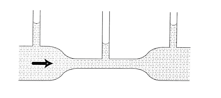
Bernoulli’s principle states that “For a fluid flowing through a tube, the sum of the pressure, the kinetic energy per unit volume and the potential energy per unit volume of the fluid is a constant”. Mathematically expressed as;P + ½ ρ v2 + ρ g h = constant. Where P – pressure, ρ – density, v= velocity, g – acceleration due to gravity and h – height.
Bernoulli’s effect
When air is blown through the tunnel formed, the area marked ‘T’ collapses inwards showing that pressure outside is more than the one inside the tunnel.
The pressure inside the tunnel decreases as the air through it increases in speed.
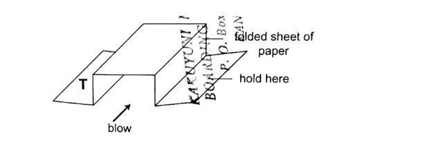
Applications of Bernoulli’s principle.1. Car carburetor– inside the carburetor the air passage is partially constricted at the point where petrol mixes with air hence air intake increases the speed of air while decreasing the pressure inside for petrol to vaporize quickly before it gets to the cylinder where combustion occurs.
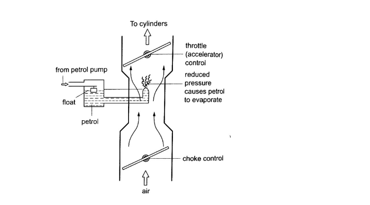
2. Horizontal pipe – for a streamline flow through a pipe the term ρ g h is eliminated from the Bernoulli’s equation leaving P + ½ ρ v2 = constant, indicating that pressure in liquid is greatest when speed is least.When this is combined with the equation of continuity, the pressure is then greatest when the pipe is widest hence the following observation.
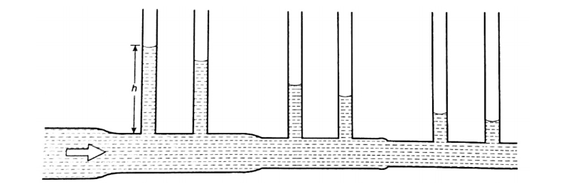
3. Dynamic lift – when air is blown at the top a flat sheet of paper the ends of the paper moves upward and this because the speed of air on top of the paper is greater than below and according to Bernoulli’s principle the pressure on top lowers and the pressure below becomes sufficient enough to produce a force which moves the paper upwards.This is what is referred to as the dynamic lift since it is caused by motion.
The upward force is equal to the product of the pressure difference and the area of the surface lifted.
It is applied in the taking off of air-planes, the trajectory of a spinning ball, paint sprayer and Bunsen burner among others.
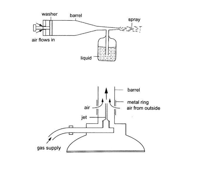
Physics Notes Form 3Physics Form Three
Chapter One
Linear Motion
Introduction
Study of motion is divided into two;
1. Kinematics
2. Dynamics
In kinematics forces causing motion are disregarded while dynamics deals with motion of objects and the forces causing them.
I. Displacement
Distance moved by a body in a specified direction is called displacement. It is denoted by letter‘s’ and has both magnitude and direction. Distance is the movement from one point to another. The Si unit for displacement is the metre (m).
II. Speed
This is the distance covered per unit time.
Speed= distance covered/ time taken. Distance is a scalar quantity since it has magnitude only.
The SI unit for speed is metres per second(m/s or ms-1)
Average speed= total distance covered/total time taken Other units for speed used are Km/h.
Examples
1. A body covers a distance of 10m in 4 seconds. It rests for 10 seconds and finally covers a distance of 90m in 60 seconds. Calculate the average speed.
Solution
Total distance covered =10+90= 100m
Total time taken =4+10+6= 20 seconds
Therefore average speed = 100/20= 5m/s
2. Calculate the distance in metres covered by a body moving with a uniform speed of 180 km/h in 30 seconds.
Solution
Distance covered=speed*time
=180*1000/60*60=50m/s
=50*30
=1,500m
3. Calculate the time in seconds taken a by body moving with a uniform speed of 360km/h to cover a distance of 3,000 km?
Solution
Speed:360km/h=360*1000/60*60=100m/s
Time=distance/speed
3000*1000/100
=30,000 seconds.
III. Velocity
This is the change of displacement per unit time. It is a vector quantity.
Velocity=change in displacement/total time taken
The SI units for velocity are m/s
Examples
1. A man runs 800m due North in 100 seconds, followed by 400m due South in 80 seconds. Calculate,
a. His average speed
b. His average velocity
c. His change in velocity for the whole journey
Solution
a. Average speed: total distance travelled/total time taken
=800+400/100+80
=1200/180
=6.67m/s
b. Average velocity: total displacement/total time
=800-400/180
=400/180
=2.22 m/s due North
c. Change in velocity=final-initial velocity
= (800/100)-(400-80)
=8-5
=3m/s due North
2. A tennis ball hits a vertical wall at a velocity of 10m/s and bounces off at the same velocity. Determine the change in velocity.
Solution
Initial velocity(u)=-10m/s
Final velocity (v) = 10m/s
Therefore change in velocity= v-u
=10- (-10)
=20m/s
IV. Acceleration
This is the change of velocity per unit time. It is a vector quantity symbolized by ‘a’. Acceleration ‘a’=change in velocity/time taken= v-u/t The SI units for acceleration are m/s2 Examples 1. The velocity of a body increases from 72 km/h to 144 km/h in 10 seconds.
Calculate its acceleration.
Solution
Initial velocity= 72 km/h=20m/s
Final velocity= 144 km/h=40m/s
Therefore ‘a’ =v-u/t
= 40-20/10
2m/s2
2. A car is brought to rest from 180km/h in 20 seconds. What is its retardation?
Solution
Initial velocity=180km/h=50m/s
Final velocity= 0 m/s
A = v-u/t=0-50/20
= -2.5 m/s2
Hence retardation is 2.5 m/s2
Motion graphs
Distance-time graphs
a)
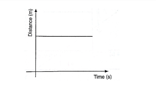
b)
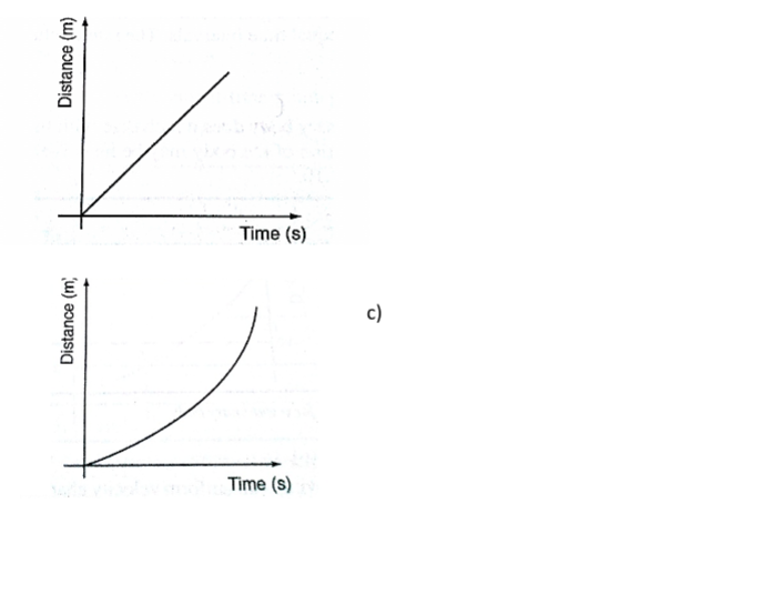
Area under velocity-time graphConsider a body with uniform or constant acceleration for time‘t’ seconds;
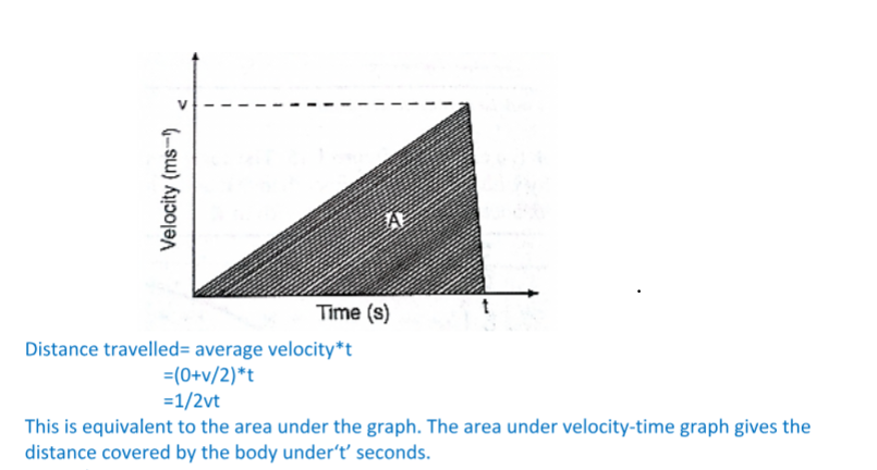
This is equivalent to the area under the graph. The area under velocity-time graph gives the distance covered by the body under‘t’ seconds.Example
A car starts from rest and attains a velocity of 72km/h in 10 seconds.
It travels at this velocity for 5 seconds and then decelerates to stop after another 6 seconds.
Draw a velocity-time graph for this motion. From the graph;
i. Calculate the total distance moved by the car
ii. Find the acceleration of the car at each stage.
Solution
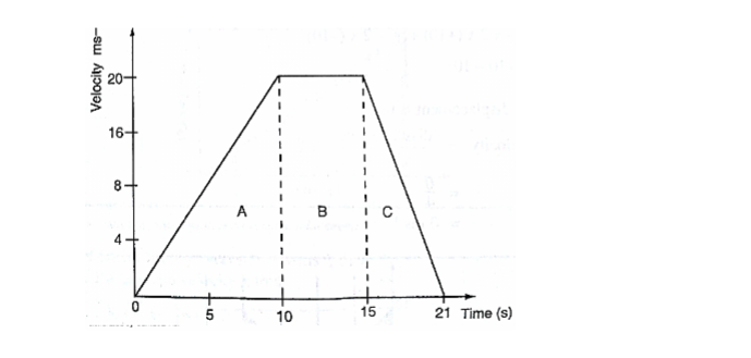
a. From the graph, total distance covered= area of (A+B+C)=(1/2×10×20)+(1/2×6×20)+(5×20)
=100+60+100
=260m
Also the area of the trapezium gives the same result.
b. Acceleration= gradient of the graph
Stage A gradient= 20-0/ 10-0 = 2 m/s2
Stage b gradient= 20-20/15-10 =0 m/s2
Stage c gradient= 0-20/21-15 =-3.33 m/s2
Using a ticker-timer to measure speed, velocity and acceleration. It will be noted that the dots pulled at different velocities will be as follows;
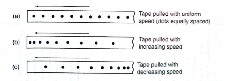
Most ticker-timers operate at a frequency of 50Hzi.e. 50 cycles per second hence they make 50 dots per second. Time interval between two consecutive dots is given as,1/50 seconds= 0.02 seconds. This time is called a tick.
The distance is measured in ten-tick intervals hence time becomes 10×0.02= 0.2 seconds.
Examples
a. A tape is pulled steadily through a ticker-timer of frequency 50 Hz.
Given the outcome below, calculate the velocity with which the tape is pulled.
Solution
Distance between two consecutive dots= 5cm
Frequency of the ticker-timer=50Hz
Time taken between two consecutive dots=1/50=0.02 seconds
Therefore, velocity of tape=5/0.02= 250 cm/s
b. The tape below was produced by a ticker-timer with a frequency of 100Hz. Find the acceleration of the object which was pulling the tape.
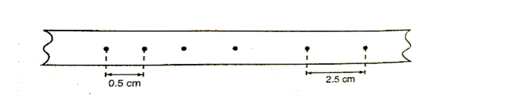
SolutionTime between successive dots=1/100=0.01 seconds
Initial velocity (u) 0.5/0.01 50 cm/s
Final velocity (v) 2.5/0.01= 250 cm/s
Time taken= 4 ×0.01 = 0.04 seconds
Therefore, acceleration= v-u/t= 250-50/0.04=5,000 cm/s2
Equations of linear motion
The following equations are applied for uniformly accelerated motion;
v = u + at
s = ut + ½ at2
v2= u2 +2as
Examples
1. A body moving with uniform acceleration of 10 m/s2 covers a distance of 320 m. if its initial velocity was 60 m/s. Calculate its final velocity.
Solution
V2 = u2 +2as
= (60) +2×10×320
=3600+6400
= 10,000
Therefore v= (10,000)1/2
v= 100m/s
2. A body whose initial velocity is 30 m/s moves with a constant retardation of 3m/s. Calculate the time taken for the body to come to rest.
Solution
v = u+at
0= 30-3t
30=3t
t= 30 seconds.
3. A body is uniformly accelerated from rest to a final velocityof 100m/s in 10 seconds. Calculate the distance covered.
Solution
s=ut+ ½ at2
=0×10+ ½ ×10×102
= 1000/2=500m
Motion under gravity.
1. Free fall
The equations used for constant acceleration can be used to become,
v =u+gt
s =ut + ½ gt2
v2= u+2gs
2. Vertical projection
Since the body goes against force of gravity then the following equations hold
v =u-gt ……………1
s =ut- ½ gt2 ……2
v2= u-2gs …………3
N.B time taken to reach maximum height is given by the following
t=u/g since v=0 (using equation 1)
Time of flight
The time taken by the projectile is the timetaken to fall back to its point ofprojection. Using eq. 2 then, displacement =0
0= ut- ½ gt2
0=2ut-gt2
t(2u-gt)=0
Hence, t=0 or t= 2u/g
t=o corresponds to the start of projection
t=2u/gcorresponds to the time of flight
The time of flight is twice the time taken to attain maximum height.
Maximum height reached.
Using equation 3 maximum height, Hmax is attained when v=0 (final velocity).
Hence v2= u2-2gs;- 0=u2-2gHmax, therefore
2gHmax=u2
Hmax=u2/2g
Velocity to return to point of projection.
At the instance of returning to the original point, total displacement equals to zero.
v2 =u2-2gs hence v2= u2
Thereforev=u or v=±u
Example
A stone is projected vertically upwards with a velocity of 30m/s from the ground.
Calculate,
a. The time it takes to attain maximum height
b. The time of flight
c. The maximum height reached
d. The velocity with which it lands on the ground. (take g=10m/s)
Solution
a. Time taken to attain maximum height
T=u/g=30/10=3 seconds
b. The time of flight
T=2t= 2×3=6 seconds
Or T=2u/g=2×30/10=6 seconds.
c. Maximum height reached
Hmax= u2/2g= 30×30/2×10= 45m
d. Velocity of landing (return)
v2= u2-2gs, but s=0,
Hence v2=u2
Thereforev=(30×30)1/2=30m/s
3. Horizontal projection
The path followed by a body (projectile) is called trajectory.
The maximum horizontal distance covered by the projectile is called range.
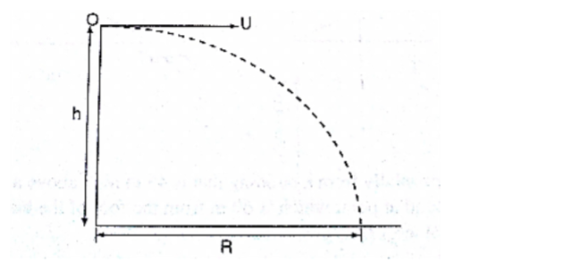
The horizontal displacement ‘R’ at a time‘t’ is given by s=ut+1/2at2 Taking u=u and a=0 hence R=ut, is the horizontal displacement and h=1/2gt2 is the vertical displacement.NOTE
The time of flight is the same as the time of free fall.
Example
A ball is thrown from the top of a cliff 20m high with a horizontal velocity of 10m/s.
Calculate,
a. The time taken by the ball to strike the ground
b. The distance from the foot of the cliff to where the ball strikes the ground.
c. The vertical velocity at the time it strikes the ground. (take g=10m/s)
Solution
a. h= ½ gt2
20= ½ ×10×t2
40=10t2
t2=40/10=4
t=2 seconds
b. R=ut
=10×2
=20m
c. v=u+at=gt
= 2×10=20m/s
Chapter Two
Refraction of Light
Introduction
Refraction is the change of direction of light rays as they pass at an angle from one medium to another of different optical densities.
Exp. To investigate the path of light through rectangular glass block.
Apparatus: – soft-board, white sheet of paper, drawing pins (optical), rectangular glass block.
Procedure
1. Fix the white plain paper on the soft board using pins.
2. Place the glass block on the paper and trace its outline, label it ABCD as shown below.
3. Draw a normal NON at point O.
4. Replace the glass block to its original position.
5. Stick two pins P1 and P2 on the line such that they are at least 6cm apart and upright.
6. Viewing pins P1 and P2 from opposite side, fixpins P3 and P4 such that they’re in a straight line.
7. Remove the pins and the glass block.
8. Draw a line joining P3 and P4 and produce it to meet the outline face AB at point O
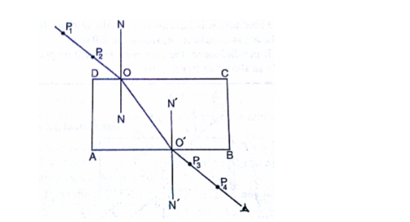
Explanation of refraction.Light travels at a velocity of 3.0×10⁸in a vacuum. Light travels with different velocities in different media. When a ray of light travels from an optically less dense media to more dense media, it is refracted towards the normal.
The glass block experiment gives rise to a very important law known as the law of reversibility which states that “if a ray of light is reversed, it always travels along its original path”.
If the glass block is parallel-sided, the emergent ray will be parallel to the incident ray but displaced laterally as shown
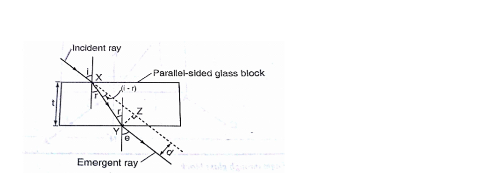
‘e’ is called the angle of emergence. The direction of the light is not altered but displaced sideways. This displacement is called lateral displacement and is denoted by‘d’.Therefore XY= t/Cos r YZ= Sin (i-r) ×xy
So, lateral displacement, d = t Sin (i-r)/Cos r
Laws of refraction
1. The incident ray, the refracted ray and the normal at the point of incidence all lie on the same plane.
2. The ratio of the sine of the angle of incidence to the sine of the angle of refraction is a constant for a given pair of media.
Sin i/sin r = constant (k)
Refractive index
Refractive index (n) is the constant of proportionality in Snell’s law; hence
Sin i/ sin r = n
Therefore sin i/sin r=n=1/sin r/sin i
Examples
1. Calculate the refractive index for light travelling from glass to air given thatang= 1.5
Solution
gna= 1/ang = 1/1.5=0.67
2. Calculate the angle of refraction for a ray of light from air striking an air-glass interface, making an angle of 600 with the interface. (ang= 1.5)
Solution
Angle of incidence (i) = 900-600=300
1.5=sin 30o/sin r, sin r =sin 300/ 1.5=0.5/1.5
Sin r=0.3333, sin-10.3333= 19.50
R= 19.50
Refractive index in terms of velocity.
Refractive index can be given in terms of velocity by the use of the following equation;
1n2 = velocity of light in medium 1/velocity of light in medium 2
When a ray of light is travelling from vacuum to a medium the refractive index is referred to as absolute refractive index of the medium denoted by ‘n’
Refractive index of a material ‘n’=velocity of light in a vacuum/velocity of light in material ‘n’
The absolute refractive indices of some common materials is given below
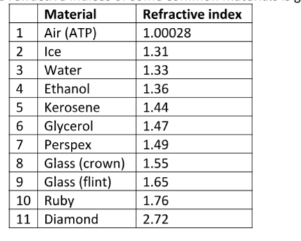
Examples 1. A ray of light is incident on a water-glass interface as shown. Calculate ‘r’. (Take the refractive index of glass and water as 3/2 and 4/3 respectively)
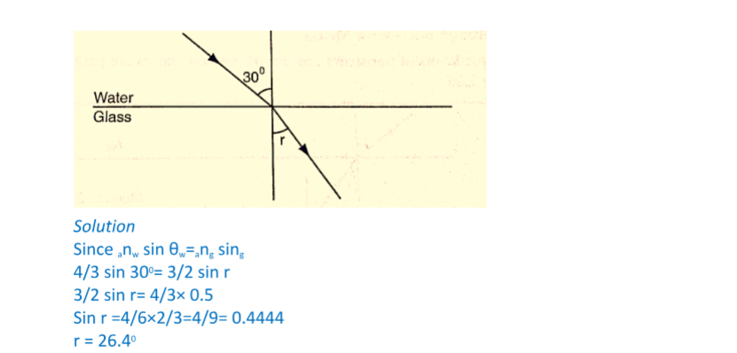
2. The refractive index of water is 4/3 and that of glass is 3/2. Calculate the refractive index of glass with respect to water.Solution
wng= gna×ang, but wna = 1/ anw=3/4
wng=3/4×3/2=9/8= 1.13
Real and apparent depth
Consider the following diagram
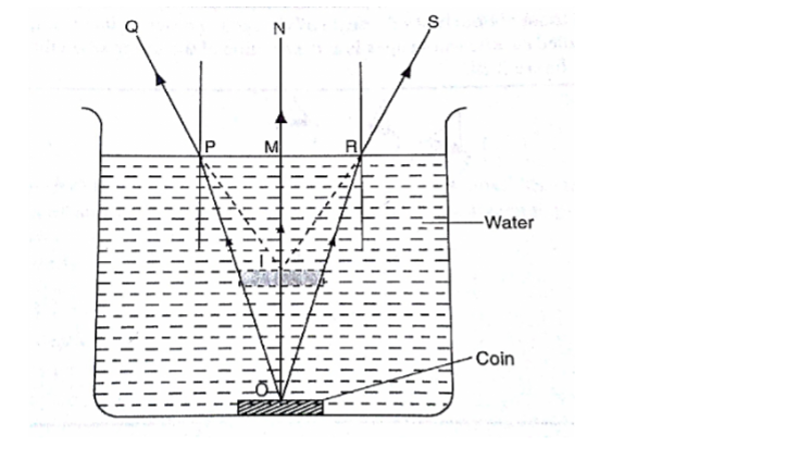
The depth of the water OM is the real depth, and the distance IM is known as the apparent depth. OI is the distance through which the coin has been displaced and is known as the vertical displacement.The relationship between refractive index and the apparent depth is given by;
Refractive index of a material=real depth/apparent depth
NB
This is true only if the object is viewed normally.
Example
A glass block of thickness 12 cm is placed on a mark drawn on a plain paper.
The mark is viewed normally through the glass. Calculate the apparent depth of the mark and hence the vertical displacement. (Refractive index of glass =3/2)
Solution
ang= real depth/apparent depth
apparent depth= real depth/ ang=(12×2)/3= 8 cm
vertical displacement= 12-8=4 cm
Applications of refractive index
Total internal reflection
This occurs when light travels from a denser optical medium to a less dense medium. The refracted ray moves away from the normal until a critical angle is reached usually 900 where the refracted ray is parallel to the boundary between the two media.
If this critical angle is exceeded total internal reflection occurs and at this point no refraction occurs but the ray is reflected internally within the denser medium.
Relationship between the critical angle and refractive index.
Consider the following diagram
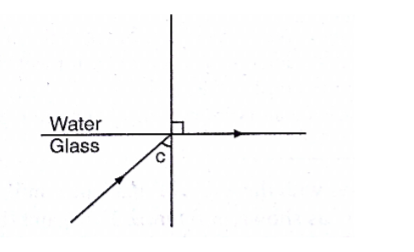
From Snell’s lawgnw = sin C/sin 900,but ang = 1/gna since sin 900 = 1
Thereforeang= 1/sin C, hence sin C=1/n or n=1/sin C
Example
Calculate the critical angle of diamond given that its refractive index is 2.42
Solution
Sin C= 1/n=1/ 2.42= 0.4132= 24.40
Effects of total internal reflection
1. Mirage: These are ‘pools of water’ seen on a tarmac road during a hot day.
They are also observed in very cold regions but the light curves in opposite direction such that a polar bear seems to be upside down in the sky.
2. Atmospheric refraction: the earths’ atmosphere refracts light rays so that the sun can be seen even when it has set. Similarly the sun is seen before it actually rises.
Applications of total internal reflection
1. Periscope: a prism periscope consists of two right angled glass prisms of angles 450,900 and 450 arranged as shown below. They are used to observe distant objects.
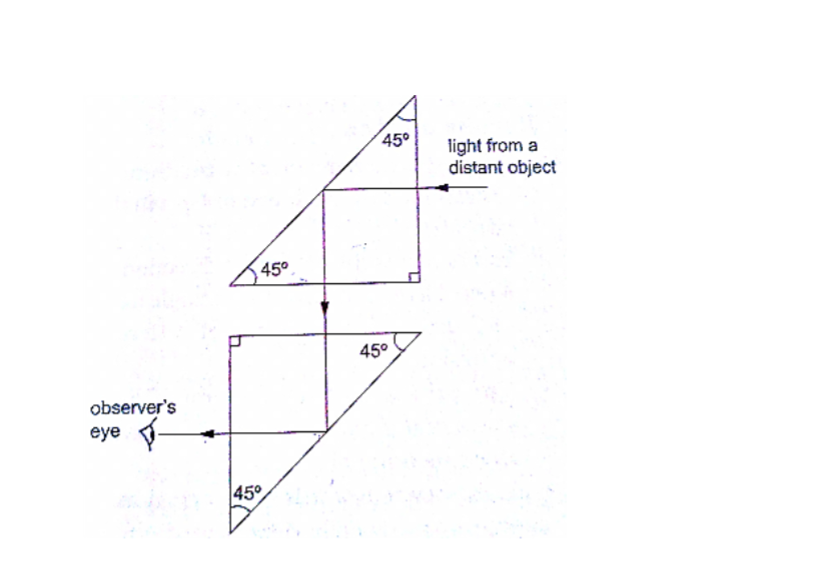
2. Prism binoculars: the arrangement of lenses and prisms is as shown below. Binoculars reduce the distance of objects such that they seem to be nearer.
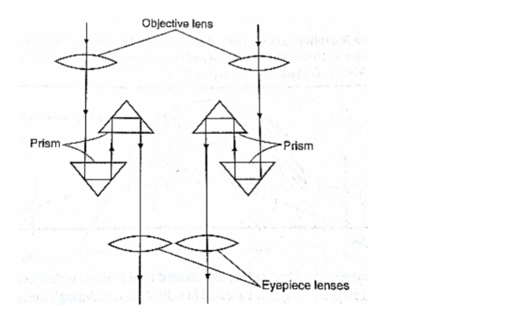
3. Pentaprism: used in cameras to change the inverted images formed into erect and actual image in front of the photographer.4. Optical fibre: this is a flexible glass rod of small diameter. A light entering through them undergoes repeated internal reflections.
They are used in medicine to observe or view internal organs of the body
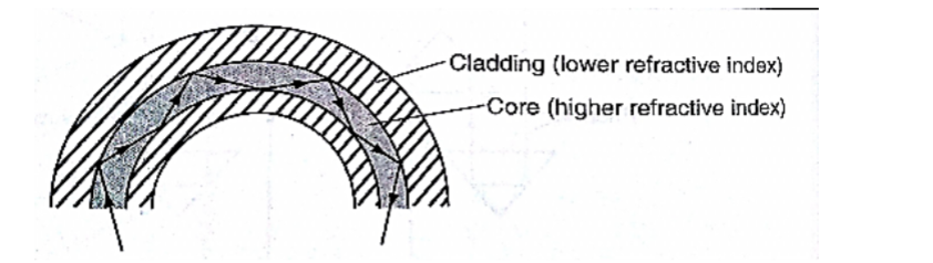
5. Dispersion of white light:the splitting of light into its constituent colours is known as dispersion. Each colour represents a different wavelength as they strike the prism and therefore refracted differently as shown.
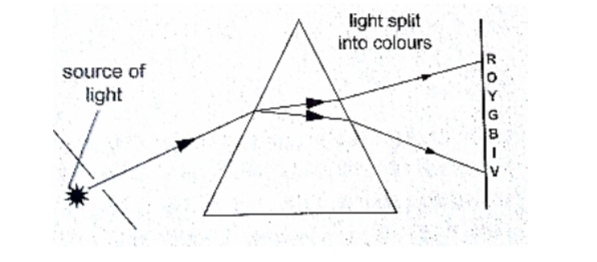
Chapter ThreeNewton’s Laws of Motion
Newton’s first law (law of inertia)
This law states that “A body continues in its state of rest or uniform motion unless an unbalanced force acts on it”.
The mass of a body is a measure of its inertia. Inertia is the property that keeps an object in its state of motion and resists any efforts to change it.
Newton’s second law (law of momentum)
Momentum of a body is defined as the product of its mass and its velocity.
Momentum ‘p’=mv. The SI unit for momentum is kgm/s or Ns.
The Newton’s second law states that “The rate of change of momentum of a body is proportional to the applied force and takes place in the direction in which the force acts”
Change in momentum= mv-mu
Rate of change of momentum= mv-mu/∆t
Generally the second law gives rise to the equation of force F=ma
Hence F=mv-mu/∆t and F∆t=mv-mu
The quantity F∆t is called impulse and is equal to the change of momentum of the body. The SI unit for impulse is Ns.
Examples
1. A van of mass 3 metric tons is travelling at a velocity of 72 km/h. Calculate the momentum of the vehicle.
Solution
Momentum=mv=72km/h=(20m/s)×3×103 kg
=6.0×10⁴kgm/s
2. A truck weighs 1.0×10⁵ N and is free to move. What force willgiveit an acceleration of 1.5 m/s2? (take g=10N/kg)
Solution
Mass of the truck = (1.0×10⁵)/10=6.0×104
Using F=ma
=1.5×10×104
=1.5×10⁴ N
3. A car of mass 1,200 kg travelling at 45 m/s is brought to rest in 9 seconds.
Calculate the average retardation of the car and the average force applied by the brakes.
Solution
Since the car comes to rest, v=0, a=(v-u)/t =(0-45)/9=-5m/s (retardation)
F=ma =(1200×-5) N =-6,000 N (braking force)
4. A truck of mass 2,000 kg starts from rest on horizontal rails. Find the speed 3 seconds after starting if the tractive force by the engine is 1,000 N.
Solution
Impulse = Ft=1,000×3= 3,000 Ns
Let v be the velocity after 3 seconds.
Since the truck was initially at rest then u=0. Change in momentum=mv-mu
= (2,000×v) – (2,000×0)
=2,000 v
But impulse=change in momentum
2,000 v = 3,000
v = 3/2=1.5 m/s.
Weight of a body in a lift or elevator
When a body is in a lift at rest then the weight
W=mg
When the lift moves upwards with acceleration ‘a’ then the weight becomes
W = m (a+g)
If the lift moves downwards with acceleration ‘a’ then the weight becomes
W = m (g-a)
Example
A girl of mass stands inside a lift which is accelerated upwards at a rate of 2 m/s2. Determine the reaction of the lift at the girls’ feet.
Solution
Let the reaction at the girls’ feet be ‘R’ and the weight ‘W’
The resultant force F= R-W
= (R-500) N
Using F = ma, then R-500= 50×2, R= 100+500 = 600 N.
Newton’s third law (law of interaction)
This law states that “For every action or force there is an equal and opposite force or reaction”
Example
A girl of mass 50 Kg stands on roller skates near a wall. She pushes herself against the wall with a force of 30N.
If the ground is horizontal and the friction on the roller skates is negligible, determine her acceleration from the wall.
Solution
Action = reaction = 30 N
Force of acceleration from the wall = 30 N
F = ma
a = F/m = 30/50 = 0.6 m/s2
Linear collisions
Linear collision occurs when two bodies collide head-on and move along the same straight line.
There are two types of collisions;
a) Inelastic collision: – this occurs when two bodies collide and stick together i.e. hitting putty on a wall. Momentum is conserved.
b) Elastic collision: – occurs when bodies collide and bounce off each other after collision. Both momentum and kinetic energy are conserved.
Collisions bring about a law derived from both Newton’s third law and conservation of momentum.
This law is known as the law of conservation of linear momentum which states that “when no outside forces act on a system of moving objects, the total momentum of the system stays constant”.
Examples
1. A bullet of mass 0.005 kg is fired from a gun of mass 0.5 kg.
If the muzzle velocity of the bullet is 300 m/s, determine the recoil velocity of the gun.
Solution
Initial momentum of the bullet and the gun is zero since they are at rest.
Momentum of the bullet after firing = (0.005×350) = 1.75 kgm/s
But momentum before firing = momentum after firing hence
0 = 1.75 + 0.5 v where ‘v’ = recoil velocity
0.5 v = -1.75
v =-1.75/0.5 = – 3.5 m/s (recoil velocity)
2. A resultant force of 12 N acts on a body of mass 2 kg for 10 seconds.
What is the change in momentum of the body?
Solution
Change in momentum = ∆P = mv – mu= Ft
= 12×10 = 12 Ns
3. A minibus of mass 1,500 kg travelling at a constant velocity of 72 km/h collides head-on with a stationary car of mass 900 kg.
The impact takes 2 seconds before the two move together at a constant velocity for 20 seconds.
Calculate
a) The common velocity
b) The distance moved after the impact
c) The impulsive force
d) The change in kinetic energy
Solution
a) Let the common velocity be ‘v’
Momentum before collision = momentum after collision
(1500×20) + (900×0) = (1500 +900)v
30,000 = 2,400v
v = 30,000/2,400 = 12.5 m/s (common velocity)
b) After impact, the two bodies move together as one with a velocity of 12.5 m/s
Distance = velocity × time
= 12.5×20
= 250m
c) Impulse = change in momentum
= 1500 (20-12.5) for minibus or
=900 (12.5 – 0) for the car
= 11,250 Ns
Impulse force F = impulse/time = 11,250/2 = 5,625 N
d) K.E before collision = ½ × 1,500 × 202 = 3 × 10⁵ J
K.E after collision = ½ × 2400 × 12.52 = 1.875×10⁵ J
Therefore, change in K.E =(3.00 – 1.875) × 105 = 1.25× 10⁵ J
Some of the applications of the law of conservation of momentum
1. Rocket and jet propulsion: – rocket propels itself forward by forcing out its exhaust gases.
The hot gases are pushed through exhaust nozzle at high velocity therefore gaining momentum to move forward.
2. The garden sprinkler: – as water passes through the nozzle at high pressure it forces the sprinkler to rotate.
Solid friction
Friction is a force which opposes or tends to oppose the relative motion of two surfaces in contact with each other.
Measuring frictional forces
We can relate weight of bodies in contact and the force between them.
This relationship is called coefficient of friction.
Coefficient of friction is defined as the ratio of the force needed to overcome friction Ff to the perpendicular force between the surfaces Fn.
Hence µ = Ff/ Fn
Examples
1. A box of mass 50 kg is dragged on a horizontal floor by means of a rope tied to its front.
If the coefficient of kinetic friction between the floor and the box is 0.30, what is the force required to move the box at uniform speed?
Solution
Ff = µFn
Fn= weight = 50×10 = 500 N
Ff = 0.30 × 500 = 150 N
2. A block of metal with a mass of 20 kg requires a horizontal force of 50 N to pull it with uniform velocity along a horizontal surface.
Calculate the coefficient of friction between the surface and the block. (take g = 10 m/s)
Solution
Since motion is uniform, the applied force is equal to the frictional force
Fn = normal reaction = weight = 20 ×10 = 200 N
Therefore, µ =Ff/ Fn = 50/ 200 = 0.25.
Laws of friction
- It is difficult to perform experiments involving friction and thus the following statements should therefore be taken merely as approximate descriptions:1. Friction is always parallel to the contact surface and in the opposite direction to the force tending to produce or producing motion.
2. Friction depends on the nature of the surfaces and materials in contact with each other.
3. Sliding (kinetic) friction is less than static friction (friction before the body starts to slide).
4. Kinetic friction is independent of speed.
5. Friction is independent of the area of contact.
6. Friction is proportional to the force pressing the two surfaces together.
Applications of friction
1. Match stick
2. Chewing food
3. Brakes
4. Motion of motor vehicles
5. Walking
Methods of reducing friction
1. Rollers
2. Ball bearings in vehicles and machines
3. Lubrication / oiling
4. Air cushioning in hovercrafts
Example
A wooden box of mass 30 kg rests on a rough floor. The coefficient of friction between the floor and the box is 0.6. Calculate
a) The force required to just move the box
b) If a force of 200 N is applied the box with what acceleration will it move?
Solution
a) Frictional force Ff= µFn = µ(mg)
= 0.6×30×10 = 180 N
b) The resultant force = 200 – 180 = 20 N
From F =ma, then 20 = 30 a
a = 20 / 30 = 0.67 m/s2
Viscosity
This is the internal friction of a fluid. Viscosity of a liquid decreases as temperature increases.
When a body is released in a viscous fluid it accelerates at first then soon attains a steady velocity called terminal velocity.
Terminal velocity is attained when F + U = mg where F is viscous force, U is upthrust and mg is weight.
Chapter Four
Energy, Work, Power and Machines
Energy
This is the ability to do work.
Forms of energy.
1. Chemical energy: – this is found in foods, oils charcoal firewood etc.
2. Mechanical energy: – there are two types;
i. Potential energy – a body possesses potential energy due to its relative position or state
ii. Kinetic energy – energy possessed by a body due to its motion i.e. wind, water
iii. Wave energy – wave energy may be produced by vibrating objects or particles i.e. light, sound or tidal waves.
iv. Electrical energy – this is energy formed by conversion of other forms of energy i.e. generators.
Transformation and conservation of energy
Any device that facilitates energy transformations is called transducer. Energy can be transformed from one form to another i.e. mechanical – electrical – heat energy.
The law of conservation of energy states that “energy cannot be created or destroyed; it can only be transformed from one form to another”.
Work
Work is done when a force acts on a body and the body moves in the direction of the force.
Work done = force × distance moved by object
W = F × d
Work is measured in Nm. 1 Nm = 1 Joule (J)
Examples
1. Calculate the work done by a stone mason lifting a stone of mass 15 kg through a height of 2.0 m. (take g=10N/kg)
Solution
Work done = force × distance
= (15× 10) × 2 = 300 Nm or 300 J
2. A girl of mass 50 kg walks up a flight of 12 steps. If each step is 30 cm high, calculate the work done by the girl climbing the stairs.
Solution
Work done = force × distance
= (50× 10) × (12 ×30) ÷ 100 = 500 × 3.6 = 1,800 J
3. A force of 7.5 N stretches a certain spring by 5 cm. How much work is done in stretching this spring by 8.0 cm?
Solution
A force of 7.5 produces an extension of 5.0 cm.
Hence 8.0 cm = (7.5 ×8)/ 5 = 12.0 N
Work done = ½ × force × extension
= ½ × 12.0 × 0.08 = 0.48 J
4. A car travelling at a speed of 72 km/h is uniformly retarded by an applicationof brakes and comes to rest after 8 seconds. If the car with its occupants has a mass of 1,250 kg. Calculate;
a) The breaking force
b) The work done in bringing it to rest
Solution
a) F = ma and a = v – u/t
But 72 km/h = 20m/s
a = 0 -20/8 = – 2.5 m/s
Retardation = 2.5 m/s Braking force F = 1,250 × 2.5
= 3,125 N
b) Work done = kinetic energy lost by the car
= ½ mv2 – ½ mu2
= ½ × 1250 × 02 – ½ × 1250 × 202
= – 2.5 × 10⁵ J
5. A spring constant k = 100 Nm is stretched to a distance of 20 cm. calculate the work done by the spring.
Solution
Work = ½ ks2
= ½ × 100 × 0.22
= 2 J
Power
Poweris the time rate of doing work or the rate of energy conversion.
Power (P)
= work done / time
P = W / t
The SI unit for power is the watt (W) or joules per second (J/s).
Examples
1. A person weighing 500 N takes 4 seconds to climb upstairs to a height of 3.0 m. what is the average power in climbing up the height?
Solution
Power = work done / time = (force × distance) / time
= (500 ×3) / 4 = 375 W
2. A box of mass 500 kg is dragged along a level ground at a speed of 12 m/s. If the force of friction between the box and floor is 1200 N. Calculate the power developed.
Solution
Power = F v
= 2,000 × 12
= 24,000 W = 24 kW.
Machines
A machine is any device that uses a force applied at one point to overcome a force at another point. Force applied is called the effort while the resisting force overcome is called load. Machines makes work easier or convenient to be done.
Three quantities dealing with machines are;-
a) Mechanical advantage (M.A.) – this is defined as the ratio of the load (L) to the effort (E). It has no units.
M.A = load (L) / effort (E)
b) Velocity ratio – this is the ratio of the distance moved by the effort to the distance moved by the load
V.R = distance moved by effort/ distance moved by the load
c) Efficiency – is obtained by dividing the work output by the work input and the getting percentage
Efficiency = (work output/work input) × 100
= (M.A / V.R) × 100
= (work done on load / work done on effort) × 100
Examples
1. A machine; the load moves 2 m when the effort moves 8 m. If an effort of 20 N is used to raise a load of 60 N, what is the efficiency of the machine?
Solution
Efficiency = (M.A / V.R) × 100 M.A = load/effort =60/20 = 3
V.R =DE/ DL = 8/2 = 4
Efficiency = ¾ × 100 = 75%
Some simple machines
a) Levers – this is a simple machine whose operation relies on the principle of moments
b) Pulleys – this is a wheel with a grooved rim used for lifting heavy loads to high levels. The can be used as a single fixed pulley, or as a block-and-tackle system.
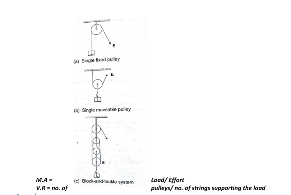
ExampleA block and tackle system has 3 pulleys in the upper fixed block and two in the lower moveable block. What load can be lifted by an effort of 200 N if the efficiency of the machine is 60%?
Solution
V.R = total number of pulleys = 5
Efficiency = (M.A /V.R) × 100 = 60%
0.6 = M.A/ 5 =3, but M.A = Load/Effort
Therefore, load = 3 ×200 = 600 N
c) Wheel and axle– consists of a large wheel of big radius attached to an axle of smaller radius.
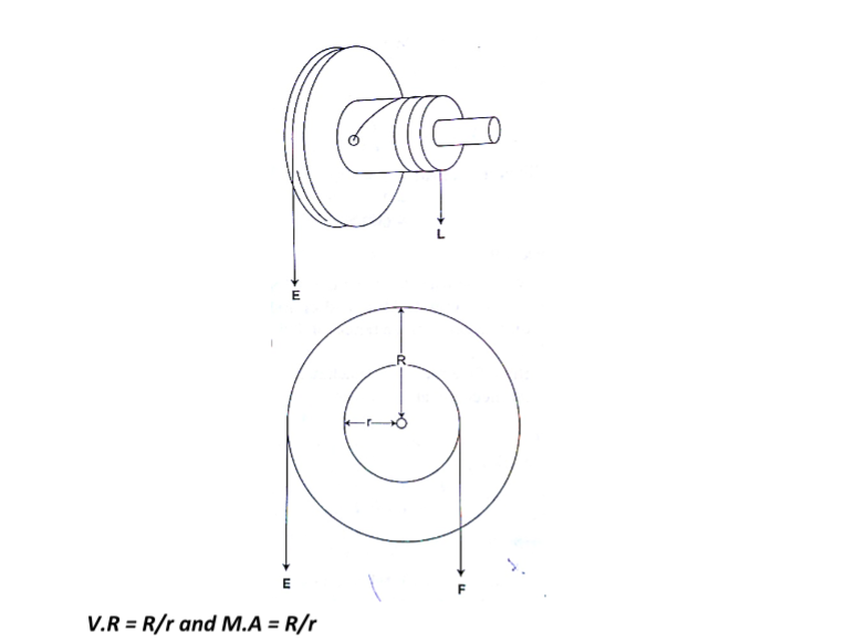
ExampleA wheel and axle is used to raise a load of 280 N by a force of 40 N applied to the rim of the wheel. If the radii of the wheel and axle are 70 cm and 5 cm respectively. Calculate the M.A, V.Rand efficiency.
Solution
M.A = 280 / 40 = 7
V.R = R/r = 70/5 = 14
Efficiency = (M.A/ V.R) × 100 = 7/14 × 100 = 50 %
d) Inclined plane:
V.R = 1/ sin θ M.A = Load/ Effort
Example
A man uses an inclined plane to lift a 50 kg load through a vertical height of 4.0 m.
the inclined plane makes an angle of 300 with the horizontal.
If the efficiency of the inclined plane is 72%, calculate;
a) The effort needed to move the load up the inclined plane at a constant velocity.
b) The work done against friction in raising the load through the height of 4.0 m. (take g= 10 N/kg)
Solution
a) V.R = 1 / sin C = 1/ sin 300 = 2 M.A = efficiency × V.R = (72/100)× 2 = 1.44
Effort = load (mg) / effort (50×10)/ 1.44 = 347.2 N
b) Work done against friction = work input – work output
Work output = mgh = 50×10×4 = 2,000 J
Work input = effort × distance moved by effort
347.2 × (4× sin 300) = 2,777.6 J
Therefore work done against friction = 2,777.6 – 2,000 = 777.6 J
e) The screw: – the distance between two successive threads is called the pitch V.R of screw = circumference of screw head / pitch P
= 2πr / P
Example
A car weighing 1,600 kg is lifted with a jack-screw of 11 mm pitch. If the handleis 28 cm from the screw, find the force applied.
Solution
Neglecting friction M.A = V.R
V.R = 2πr /P = M.A = L / E
1,600 / E = (2π× 0.28) / 0.011
E = (1,600 × 0.011 × 7) / 22×2×0.28 =10 N
f) Gears: – the wheel in which effort is applied is called the driver while the load wheel is the driven wheel.
V.R = revolutions of driver wheel / revolutions of driven wheel
Or
V.R = no.of teeth in the driven wheel/ no. of teeth in the driving wheel
Example
g) Pulley belts: -these are used in bicycles and other industrial machines V.R = radius of the driven pulley / radius of the driving pulley
h) Hydraulic machines
V.R = R2 / r2 where R- radius of the load piston and r- radius of the effort piston
Example
The radius of the effort piston of a hydraulic lift is 1.4 cm while that of the load piston is 7.0 cm.
This machine is used to raise a load of 120 kg at a constant velocity through a height of 2.5 cm. given that the machine is 80% efficient, calculate;
a) The effort needed
b) The energy wasted using the machine
Solution
a) V.R = R2 / r2 = (7×7) / 1.4 × 1.4 = 25
Efficiency = M.A / V.R = (80 /100) × 25 = 20
But M.A = Load / Effort = (120×10) / 20 = 60 N
b) Efficiency = work output / work input = work done on load (m g h) /80
= (120 × 10× 2.5) / work input
80 / 100 = 3,000 / work input
Work input = (3,000 × 100) /80 = 3,750 J
Energy wasted = work input – work output
= 3,750 – 3,000 = 750 J
Chapter Five
Current Electricity
Electric potential difference and electric current
Electric current
Electric potential difference (p. d) is defined as the work done per unit charge in moving charge from one point to another. It is measured in volts.
Electric current is the rate of flow of charge. P. d is measured using a voltmeter while current is measured using an ammeter. The SI units for charge is amperes (A).
Ammeters and voltmeters
In a circuit an ammeter is always connected in series with the battery while a voltmeter is always connected parallel to the device whose voltage is being measured.
Ohm’s law
This law gives the relationship between the voltage across a conductor and the current flowing through it.
Ohm’s law states that “the current flowing through a metal conductor is directly proportional to the potential difference across the ends of the wire provided that temperature and other physical conditions remain constant”
Mathematically V α I
So V /I = constant, this constant of proportionality is called resistance
V / I = Resistance (R)
Resistance is measured in ohms and given the symbol Ω
Examples
1. A current of 2m A flows through a conductor of resistance 2 kΩ. Calculate the voltage across the conductor.
Solution
V = IR = (2 × 10-3) × (2 × 103) = 4 V.
2. A wire of resistance 20Ω is connected across a battery of 5 V. What current is flowing in the circuit?
Solution
I = V/R = 5 / 20 = 0.25 A
Ohmic and non-ohmic conductors
Ohmic conductors are those that obey Ohms law(V α I) and a good example is nichrome wire i.e. the nichrome wire is not affected by temperature.
Non-ohmic conductors do not obey Ohms law i.e. bulb filament (tungsten), thermistor couple, semi-conductor diode etc. They are affected by temperature hence non-linear.
Factors affecting the resistance of a metallic conductor
1. Temperature – resistance increases with increase in temperature
2. Length of the conductor– increase in length increases resistance
3. Cross-sectional area– resistance is inversely proportional to the cross-sectional area of a conductor of the same material.
Resistivity of a material is numerically equal to the resistance of a material of unit length and unit cross-sectional area. It is symbolized by ρ and the units are ohmmeter (Ωm).
It is given by the following formula;
ρ = AR /lwhere A – cross-sectional area, R – resistance, l – length
Example
Given that the resistivity of nichrome is 1.1× 10⁻⁶Ωm, what length of nichrome wire of diameter 0.42 mm is needed to make a resistance of 20 Ω?
Solution
ρ = AR /l, hence l = RA/ ρ = 20 × 3.142 × (2.1×10-4) / 1.1 × 10-6 = 2.52 m
Resistors
Resistors are used to regulate or control the magnitude of current and voltage in a circuit according to Ohms law.
Types of resistors
i) Fixed resistors – they are wire-wound or carbon resistors and are designed togive a fixed resistance.
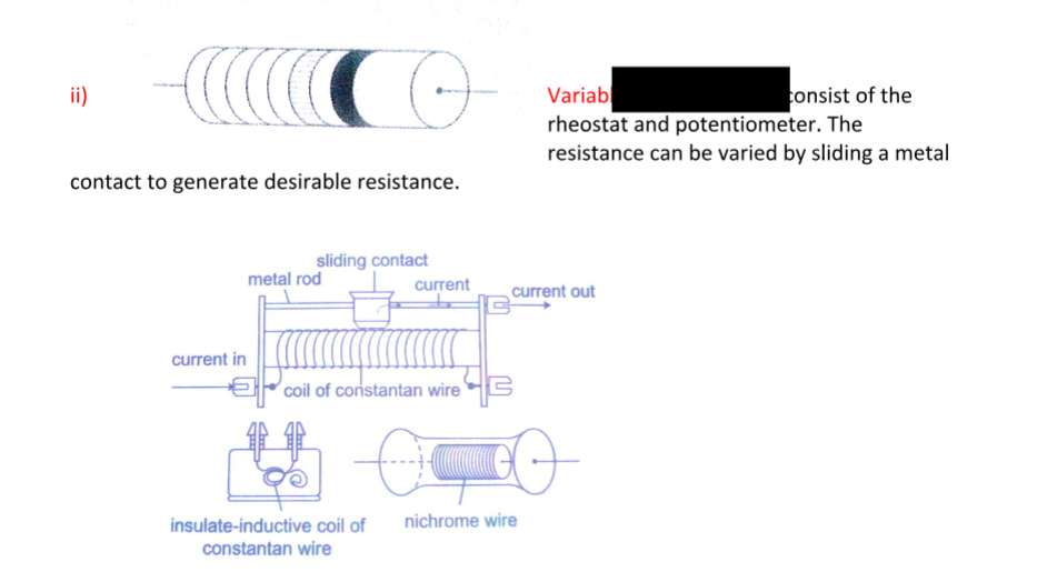
ii) Variable resistors – they consist of the rheostat and potentiometer. The resistance can be varied by sliding a metal contact to generate desirable resistance.Resistor combination
a) Series combination
Consider the following loop
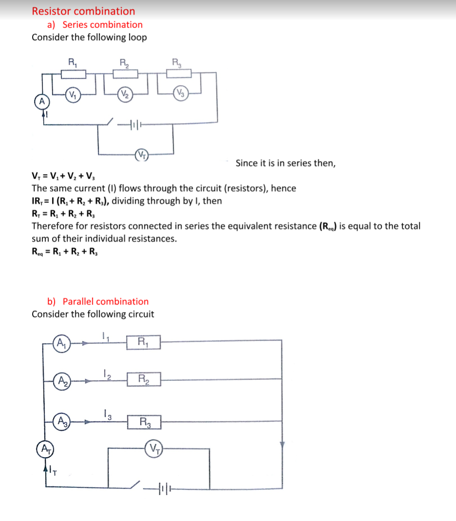
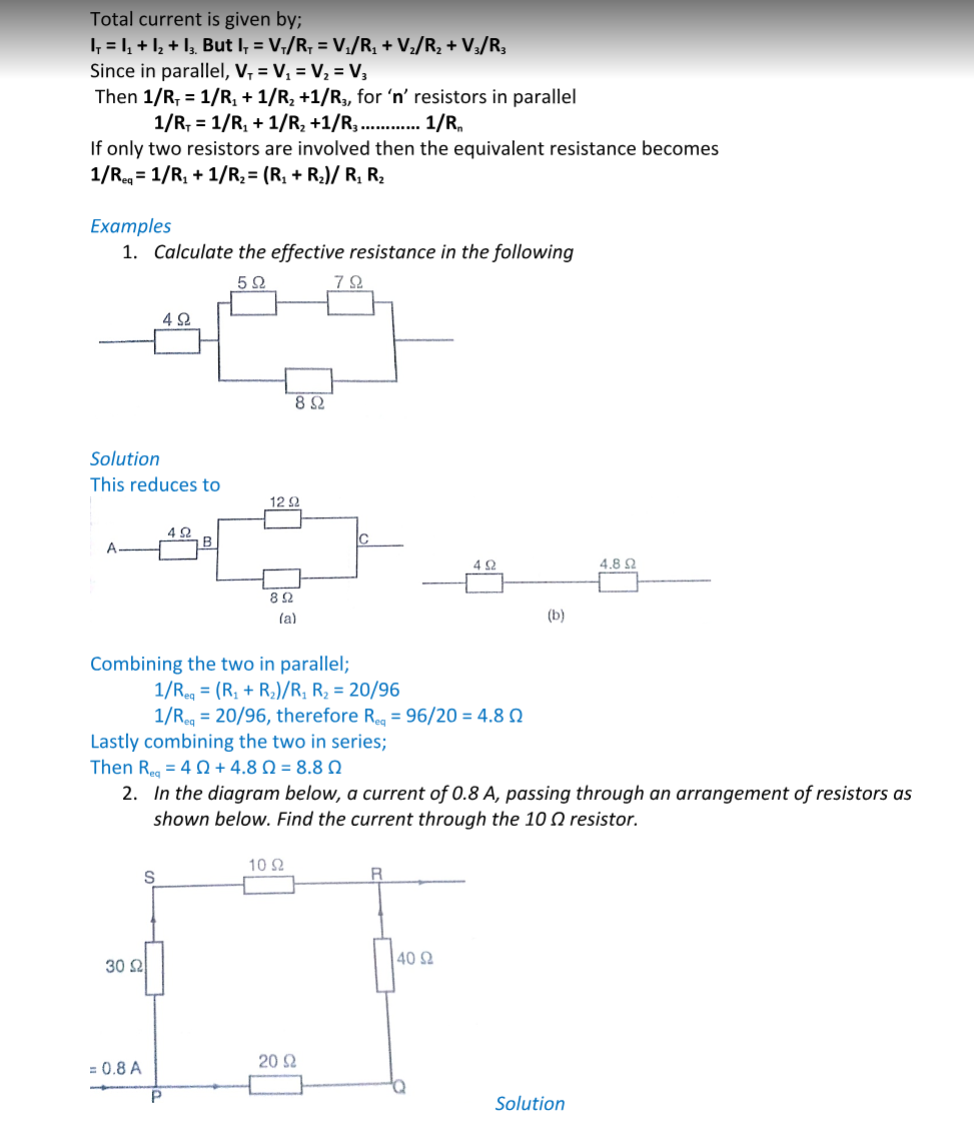
Combining those in series then this can be replaced by two resistors of 60 Ω and 40 Ω.Current through 10 Ω = (p.d. between P and R)/ (30 + 10) Ω
p.d between P and R = 0.8 × Req. Req = (40 × 60)/ 40 + 60 = 2400/ 100 = 24 Ω
p.d across R and P = 0.8 × 24 (V=IR)
therefore, current through 10 Ω = 19.2 / 10 + 30 = 0.48 A
Electromotive force and internal resistance
Electromotive force (e.m.f.) is the p.d across a cell when no current is being drawn from the cell.
The p.d across the cell when the circuit is closed is referred to as the terminal voltage of the cell.
Internal resistance of a cell is therefore the resistance of flow of current that they generate. Consider the following diagram;
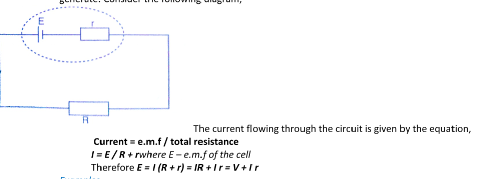
The current flowing through the circuit is given by the equation,Current = e.m.f / total resistance
I = E / R + rwhere E – e.m.f of the cell
Therefore E = I (R + r) = IR + I r = V + I r
Examples
1. A cell drives a current of 0.6 A through a resistance of 2 Ω. if the value of resistance is increased to 7 Ω the current becomes 0.2 A.
calculate the value of e.m.f of the cell and its internal resistance.
Solution
Let the internal resistance be ‘r’ and e.m.f be ‘E’.
Using E = V + I r = IR + I r
Substitute for the two sets of values for I and R
E = 0.6 × (2 + 0.6 r) = 1.2 + 0.36 r
E = 0.6 × (7 × 0.2 r) = 1.4 + 0.12 r
Solving the two simultaneously, we have,
E = 1.5 v and R = 0.5 Ω
2. A battery consists of two identical cells, each of e.m.f 1.5 v and internal resistance of 0.6 Ω, connected in parallel. Calculate the current the battery drives through a 0.7 Ω resistor.
Solution
When two identical cells are connected in series, the equivalent e.m.f is equal to that of only one cell.
The equivalent internal resistance is equal to that of two such resistance connected in parallel.
Hence Req = R1 R2 / R1 + R2 = (0.6 × 0.6) / 0.6 + 0.6 = 0.36 / 1.2 = 0.3 Ω
Equivalent e.m.f =1.5 / (0.7 + 0.3) = 1.5 A
Hence current flowing through 0.7 Ω resistor is 1.5 A
Chapter Six
Waves II
Properties of waves
Waves exhibit various properties which can be conveniently demonstrated using the ripple tank.
It consists of a transparent tray filled with water and a white screen as the bottom. On top we have a source of light.
A small electric motor (vibrator) is connected to cause the disturbance which produces waves.
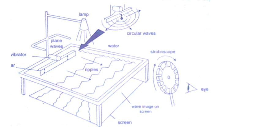
The wave fronts represent wave patterns as they move along.Rectilinear propagation
This is the property of the waves travelling in straight lines and perpendicular to the wave front.
The following diagrams represent rectilinear propagation of water waves.
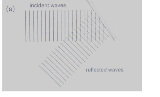
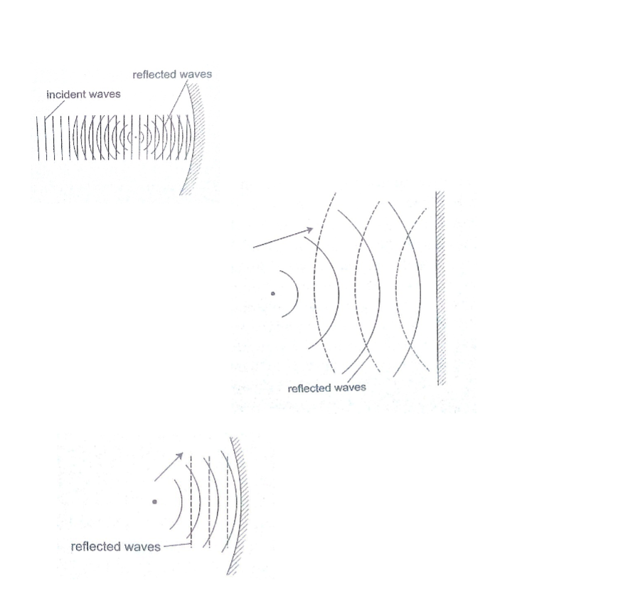
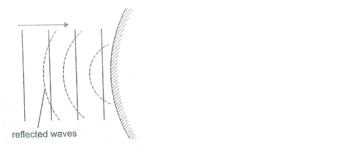
RefractionThis is the change of direction of waves at a boundary when they move from one medium to another.
This occurs when an obstacle is placed in the path of the waves. The change of direction occurs at the boundary between deep and shallow waters and only when the waves hit the boundary at an angle.
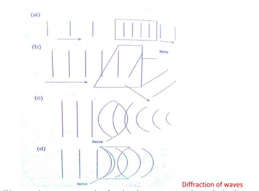
Diffraction of wavesThis occurs when waves pass an edge of an obstacle or a narrow gap, they tend to bend around the corner and spread out beyond the obstacle or gap.
Interference of wavesThis occurs when two waves merge and the result can be a much larger wave, smaller wave or no wave at all.
When the waves are in phase they add up and reinforce each other. This is called a constructive interference and when out of phase they cancel each other out and this is known as destructive interference.
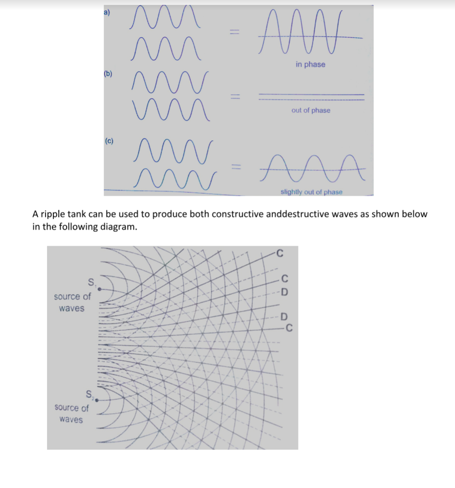
Interference in soundTwo loud speakers L1 and L2 are connected to the same signal generator so that sound waves from each of them are in phase.
The two speakers are separated by a distance of the order of wavelengths i.e. 0.5 m apart for sound frequency of 1,000 Hz.
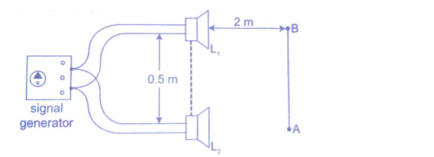
If you walk along line AB about 2m away from the speakers, the intensity of sound rises and falls alternately hence both destructive and constructive interference will be experienced.Stationary waves
They are also known as standing waves and are formed when two equal progressive waves travelling in opposite direction are superposed on each other.
When the two speakers are placed facing each other they produce standing waves.
A rope tied at one end will still produce stationary waves.
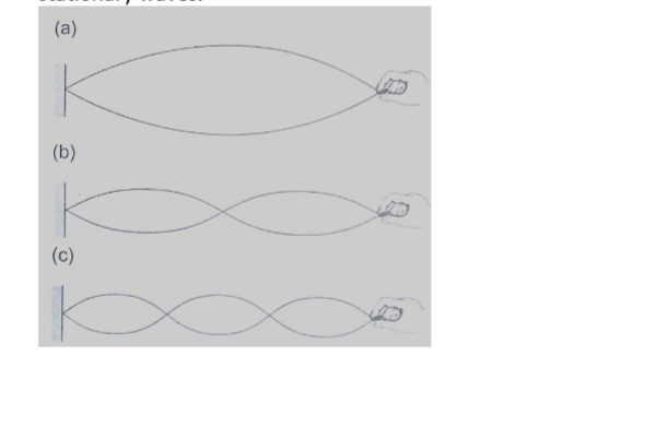
Chapter SevenElectrostatics II
Electric fields
An electric field is the space around a charged body where another charged body would be acted on by a force. These fields are represented by lines of force.
This line of force also called an electric flux line points in the direction of the force.
Electric field patterns
Just like in magnetic fields, the closeness of the electric field-lines of force is the measure of the field strength.
Their direction is always from the north or positive to the south or negative.
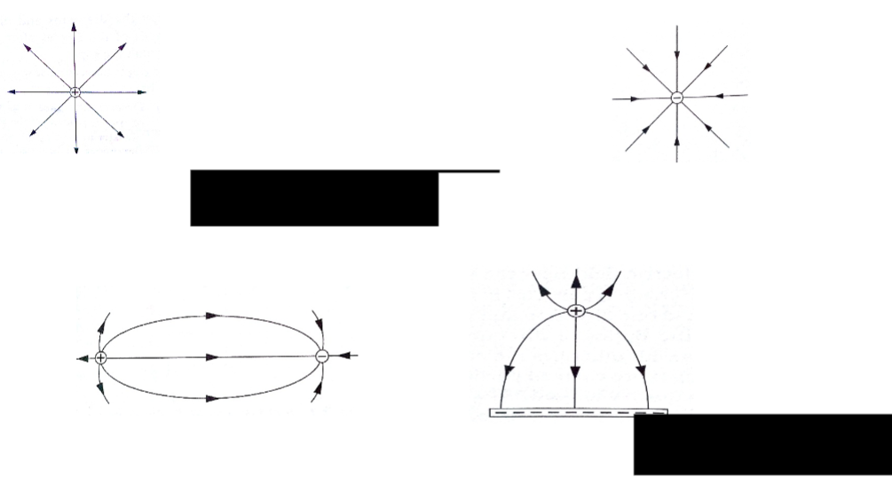
Charge distribution on conductors’ surfaceA proof plane is used to determine charge distribution on spherical or pear-shaped conductors.
For an isolated sphere it is found that the effect is the same for all points on the surface meaning that the charge is evenly distributed on all points on the spherical surface.
For appear-shaped conductor the charge is found to be denser in the regions of large curvature (small radius).
The density of charge is greatest where curvature is greatest.
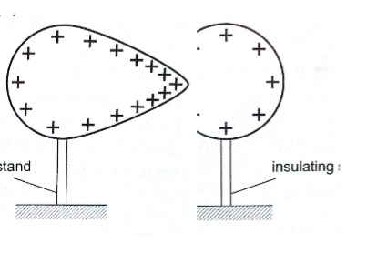
Charges on or action at sharp pointsA moving mass of air forms a body with sharp points.
The loss of electrons by molecules (ionization) makes the molecules positively charged ions.
These ions tend to move in different directions and collide producing more charged particles and this makes the air highly ionized.
When two positively charged bodies are placed close to each other, the air around them may cause a spark discharge which is a rush of electrons across the ionized gap, producing heat, light and sound in the process which lasts for a short time.
Ionization at sharp projections of isolated charged bodies may sometimes be sufficient to cause a discharge.
This discharge produces a glow called corona discharge observed at night on masts of ships moving on oceans.
The same glow is observed on the trailing edges of aircrafts.
This glow in aircrafts and ships is called St. Elmo’s fire. Aircrafts are fitted with ‘pig tails’ on the wings to discharge easily.
The lightning arrestors
Lightning is a huge discharge where a large amount of charge rushes to meet the opposite charge.
It can occur between clouds or the cloud and the earth. Lightning may not be prevented but protection from its destruction may be done through arrestors.
An arrestor consists of a thick copper strip fixed to the outside wall of a building with sharp spikes.
Capacitors and capacitance
A capacitor is a device used for storing charge.
It consists of two or more plates separated by either a vacuum or air.
The insulating material is called ‘dielectric’. They are symbolized as shown below,
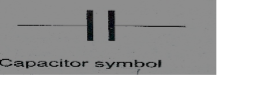
Capacitance C = Q / V where Q- charge and V – voltage.The units for capacitance are coulombs per volt (Coul /volt) and are called farads.
1 Coul/ volt = 1 farad (F)
1 µF = 10-6 F and 1pF = 10-12
Types of capacitors are;
a) Paper capacitors
b) Electrolyte capacitors
c) Variable capacitors
d) Plastic capacitors
e) Ceramic capacitors
f) Mica capacitors
Factors affecting the capacitance of a parallel-plate capacitor
1. Distance between the plates: – reducing separation increases capacitance but the plates should not be very close to avoid ionization which may lead to discharge.
2. Area of plate: – reduction of the effective area leads to reduction in capacitance.
3. Dielectric material between plates: – different materials will produce different capacitance effects.
Charging and discharging a capacitor
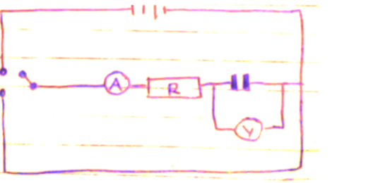
When the switch S1 is closed the capacitor charges through resistor R and discharges through the same resistor when switch S2 is closed.Applications of capacitors
1. Variable capacitor: – used in tuning radios to enable it transmit in different frequencies.
2. Paper capacitors: – used in mains supply and high voltage installations.
3. Electrolytic capacitors: – used in transistor circuits where large capacitance values are required.
Other capacitors are used in reducing sparking as a car is ignited, smoothing rectified current and increasing efficiency in a. c. power transmission.
Example
A capacitor of two parallel plates separated by air has a capacitance of 15pF.
A potential difference of 24 volts is applied across the plates,
a) Determine the charge on the capacitors.
b) When the space is filled with mica, the capacitance increases to 250pF.
How much more charge can be put on the capacitor using a 24 V supply?
Solution
: a) C= Q / V then Q = VC, hence Q = (1.5 × 10-12) × 24 = 3.6 × 10⁻¹⁰ Coul.
b) Mica C = 250pF, Q = (250 × 10-12) × 24 = 6 × 10⁻⁹ Coul.
Additional charge = (6 × 10⁻⁹) – (3.6 × 10⁻¹⁰) = 5.64 × 10⁻⁹ Coul.
Capacitor combination
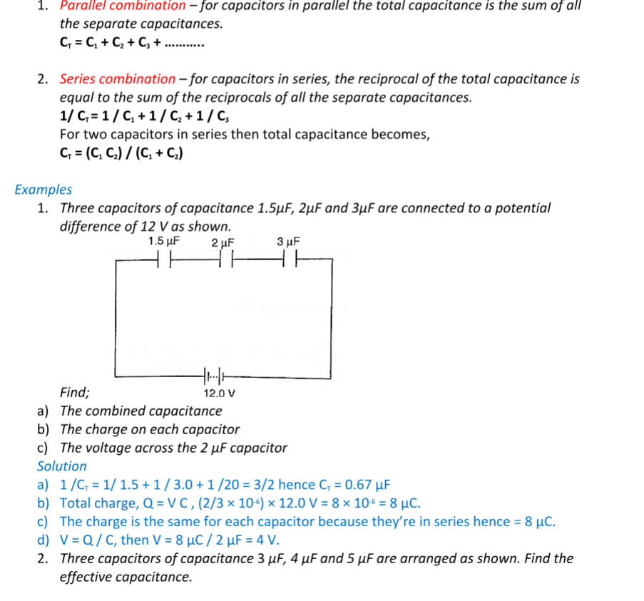
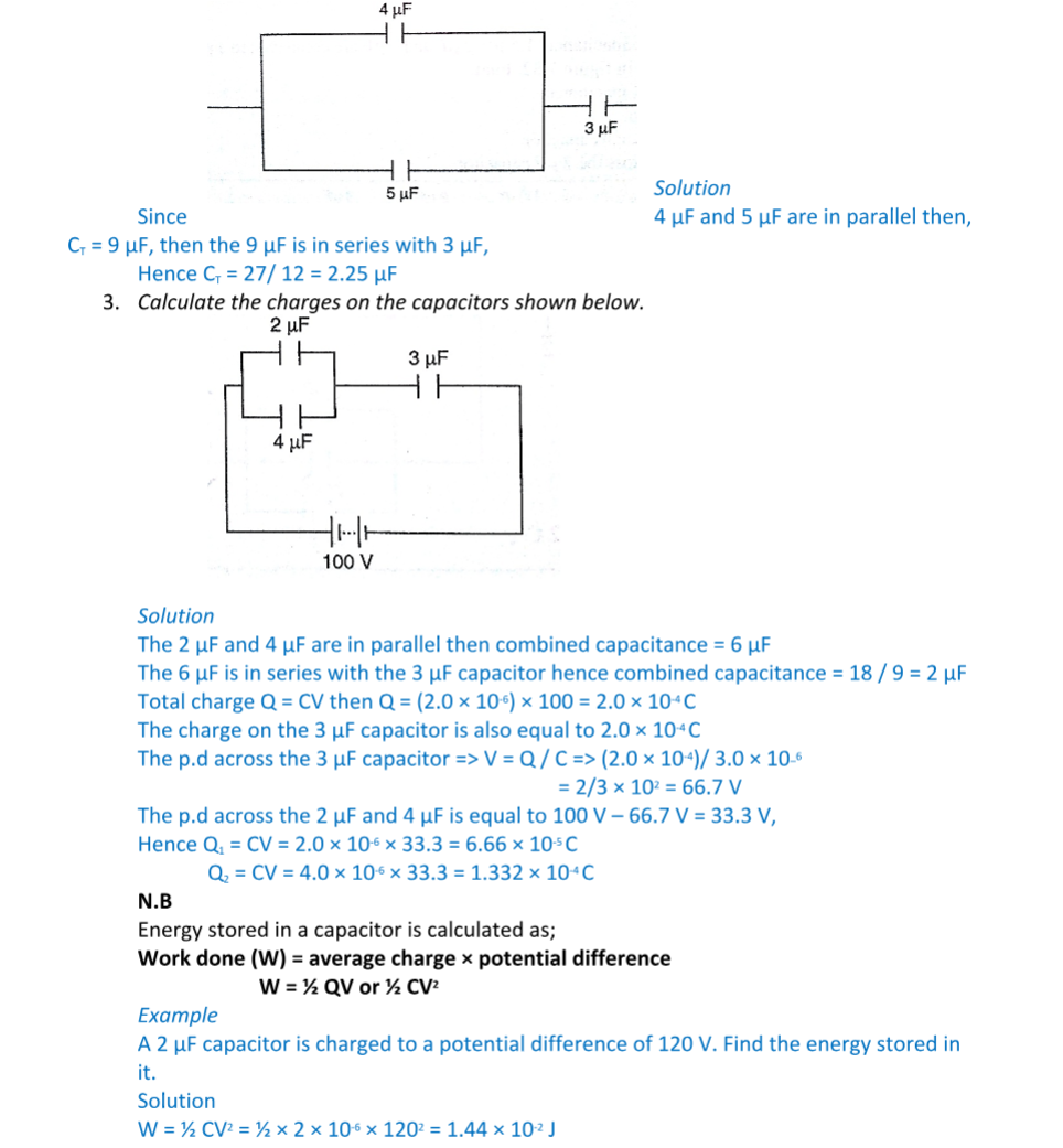
Chapter EightHeating Effect of an Electric Current
When current flows, electrical energy is transformed into other forms of energy i.e. light, mechanical and chemical changes.
Factors affecting electrical heating
Energy dissipated by current or work done as current flows depends on,
a) Current
b) Resistance
c) Time
This formula summarizes these factors as, E = I2 R t, E = I V t or E = V2 t / R
Examples
1. An iron box has a resistance coil of 30 Ω and takes a current of 10 A. Calculate the heat in kJ developed in 1 minute.
Solution
E = I2 R t = 102 × 30 × 60 = 18 × 104 = 180 kJ
2. A heating coil providing 3,600 J/min is required when the p.d across it is 24 V. Calculate the length of the wire making the coil given that its cross-sectional area is 1 × 10⁻⁷ m2 and resistivity 1 × 10⁻⁶ Ω m.
Solution
E = P t hence P = E / t = 3,600 / 60 = 60 W
P = V2 / R therefore R = (24 × 24)/ 60 = 9.6 Ω
R = ρ l/ A, l = (RA) / ρ = (9.6 × 1 × 10-7) / 1 × 10-6 = 0.96 m
Electrical energy and power
In summary, electrical power consumed by an electrical appliance is given by;
P = V I
P = I2 R
P = V2 / R
The SI unit for power is the watt (W)
1 W = 1 J/s and 1kW = 1,000 W.
Examples
1. What is the maximum number of 100 W bulbs which can be safely run from a 240 V source supplying a current of 5 A?
Solution
Let the maximum number of bulbs be ‘n’. Then 240 × 5 = 100 n
So ‘n’ = (240 × 5)/ 100 = 12 bulbs.
2. An electric light bulb has a filament of resistance 470 Ω.
The leads connecting the bulb to the 240 V mains have a total resistance of 10 Ω. Find the power dissipated in the bulb and in the leads.
Solution
Req = 470 + 10 = 480 Ω, therefore I = 240 / 480 = 0.5 A.
Hence power dissipated = I2 R = (0.5)2 × 470 = 117.5 W (bulb alone)
For the leads alone, R = 10 Ω and I = 0.5 A
Therefore power dissipated = (0.5)2 × 10 = 2.5 W.
Applications of heating of electrical current
1. Filament lamp – the filament is made up of tungsten, a metal with high melting point (3.400 0C). It is enclosed in aglass bulb with air removed and argon or nitrogen injected to avoid oxidation. This extends the life of the filament.
2. Fluorescent lamps – when the lamp is switched on, the mercury vapour emits ultra violet radiation making the powder in the tube fluoresce i.e. emit light. Different powders emit different colours.
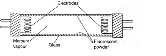
3. Electrical heating – electrical fires, cookers e.tc. their elements are made up nichrome ( alloy of nickel and chromium) which is not oxidized easily when it turns red hot.
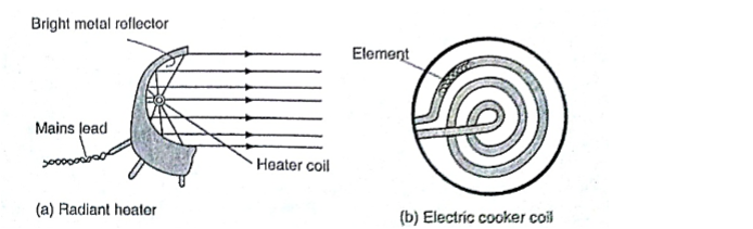
4. Fuse – this is a short length of wire of a material with low melting point (often thinned copper) which melts when current through it exceeds a certain value. They are used to avoid overloading.
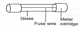
Chapter NineQuantity of Heat
Heat is a form of energy that flows from one body to another due to temperature differences between them.
Heat capacity
Heat capacity is defined as the quantity of heat required to raise the temperature of a given mass of a substance by one degree Celsius or one Kelvin. It is denoted by ‘C’.
Heat capacity, C = heat absorbed, Q / temperature change θ.
The units of heat capacity are J / 0C or J / K.
Specific heat capacity.
S.H.C of a substance is the quantity of heat required to raise the temperature of 1 kg of a substance by 1 0C or 1 K. It is denoted by ‘c’, hence,
c = Q / m θ where Q – quantity of heat, m – mass andθ – change in temperature.
The units for ‘c’ are J kg-1 K-1. Also Q = m c θ.
Examples
1. A block of metal of mass 1.5 kg which is suitably insulated is heated from 30 0C to 50 0C in 8 minutes and 20 seconds by an electric heater coil rated 54 watts.
Find;
a) The quantity of heat supplied by the heater
b) The heat capacity of the block
c) Its specific heat capacity
Solution
a) Quantity of heat = power × time = P t
= 54 × 500 = 27,000 J
b) Heat capacity, C = Q / θ = 27,000 / (50 – 30) = 1,350 J Kg-1 K-1
c) Specific heat capacity, c = C / m = 1,350 / 1.5 = 900 J Kg-1
2. If 300 g of paraffin is heated with an immersion heater rated 40 W, what is the temperature after 3 minutes if the initial temperature was 20 0C? (S.H.C for paraffin = 2,200 JK -1 K-1). Solution
Energy = P t = m c θ = Q = quantity of heat.
P t = 40 × 180 = 7,200 J
m = 0.30 kg c = 2,200, θ = ..?
Q = m c θ, θ = Q / m c = 7,200 / (0.3 × 2,200) = 10.9 0C
3. A piece of copper of mass 60 g and specific heat capacity 390 J Kg-1 K-1 cools from 90 0C to 40 0C. Find the quantity of heat given out.
Solution
Q = m c θ, = 60 × 10-3 × 390 × 50 = 1,170 J.
Determination of specific heat capacity
: A calorimeter is used to determine the specific heat capacity of a substance.
This uses the principle of heat gained by a substance is equal to the heat lost by another substance in contact with each other until equilibrium is achieved.
Heat losses in calorimeter are controlled such that no losses occur or they are very minimal.
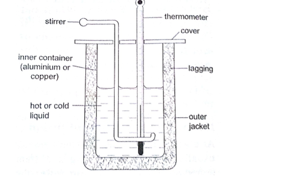
Examples1. A 50 W heating coil is immersed in a liquid contained in an insulated flask of negligible heat capacity.
If the mass of the liquid is 10 g and its temperature increases by 10 0C in 2 minutes, find the specific heat capacity of the liquid.
Solution
Heat delivered (P t) = 50 × 2 × 60 = 2,400 J
Heat gained = 0.1 × c × 10 J
Therefore ‘c’ = 2,400 / 0.1 × 10 = 2,400 J Kg-1 K-1 2. A metal cylinder mass 0.5 kg is heated electrically.
If the voltmeter reads 15V, the ammeter 0.3A and the temperatures of the block rises from 20 0C to 85 0C in ten minutes.
Calculate the specific heat capacity of the metal cylinder.
Solution
Heat gained = heat lost, V I t = m c θ
15 × 3 × 10 × 60 = 0.5 × c × 65
c = (15 × 3 × 600)/ 0.5 × 65 = 831 J Kg-1 K-1
Fusion and latent heat of fusion
Fusion is the change of state from solid to liquid.
Change of state from liquid to solid is called solidification.
Latent heat of fusion is the heat energy absorbed or given out during fusion. Specific latent heat of fusion of a substance is the quantity of heat energy required to change completely 1 kg of a substance at its melting point into liquid without change in temperature.
It is represented by the symbol (L), we use the following formula, Q = m Lf
Different substances have different latent heat of fusion.
Factors affecting the melting point
a) Pressure
b) Dissolved substances
Specific latent heat of vaporization is the quantity of heat required to change completely 1 kg of a liquid at its normal boiling point to vapour without changing its temperature.
Hence
Q = m Lv
The SI unit for specific latent heat of vaporization is J / Kg.
Example
An immersion heater rated 600 W is placed in water. After the water starts to boil, the heater is left on for 6 minutes.
It is found that the mass of the water had reduced by 0.10 kg in that time.
Estimate the specific heat of vaporization of steam.
Solution
Heat given out by the heater = P t = 600 × 6 × 60
Heat absorbed by steam = 0.10 × L v
Heat gained = heat lost, therefore, 600 × 6 × 60 = 0.10 × L v = 2.16 × 10⁶ J / Kg
Evaporation
Factors affecting the rate of evaporation
a) Temperature
b) Surface area
c) Draught (hot and dry surrounding)
d) Humidity
Comparison between boiling and evaporation Evaporation Boiling
1. Takes place at all temperature – takes place at a specific temperature
2. Takes place on the surface (no bubbles formed)- takes place throughout the liquid ( bubbles formed)
3. Decrease in atmospheric pressure increases the rate –decreases as atmospheric pressure lowers
Applications of cooling by evaporation
a) Sweating
b) Cooling of water in a porous pot
c) The refrigerator
Chapter Ten
The Gas Laws
Pressure law This law states that “the pressure of a fixed mass of a gas is directly proportional to the absolute temperature if the volume is kept constant”. The comparison between Kelvin scale and degrees Celsius is given by; θ0 = (273 + θ) K, and T (K) = (T – 273) 0C.
Examples
1. A gas in a fixed volume container has a pressure of 1.6 × 10⁵ Pa at a temperature of 27 0C.
What will be the pressure of the gas if the container is heated to a temperature of 2770C?
Solution
Since law applies for Kelvin scale, convert the temperature to kelvin
T1 = 270C = (273 + 27) K = 300 K
T2 = 2270C = (273 + 277) = 550 K
P1 / T1 = P2 / T2, therefore P2 = (1.6 × 105) × 550 / 300 = 2.93 × 10⁵ Pa.
2. At 200C, the pressure of a gas is 50 cm of mercury. At what temperature would the pressure of the gas fall to 10 cm of mercury?
Solution
P / T = constant, P1 / T1 = P2 / T2, therefore T2= (293 × 10) / 50 = 58.6 K or (– 214.4 0C)
Charles law
Charles law states that “the volume of a fixed mass of a gas is directly proportional to its absolute temperature (Kelvin) provided the pressure is kept constant”. Mathematically expressed as follows,
V1 / T1 = V2 / T2
Examples
1. A gas has a volume of 20 cm3 at 270C and normal atmospheric pressure.
Calculate the new volume of the gas if it is heated to 540C at the same pressure.
Solution
Using, V1 / T1 = V2 / T2, then V2 =(20 × 327) / 300 = 21.8 cm3.
2. 0.02m3 of a gas is at 27 0C is heated at a constant pressure until the volume is 0.03 m3. Calculate the final temperature of the gas in 0C.
Solution
Since V1 / T1 = V2 / T2, T2 = (300 × 0.03) / 0.02 = 450 K 0r 1770C
Boyle’s law
Boyle’s law states that “the pressure of a fixed mass of a gas is inversely proportional to its volume provided the temperature of the gas is kept constant”.
Mathematically expressed as,
P1 V1 = P2 V2
Examples
1. A gas in a cylinder occupies a volume of 465 ml when at a pressure equivalent to 725 mm of mercury. If the temperature is held constant, what will be the volume of the gas when the pressure on it is raised to 825 mm of mercury?
Solution
Using, P2 V1 = P2 V2, then V2 = (725 × 465) / 825 = 409 ml.
2. The volume of air 26 cm long is trapped by a mercury thread 5 cm long as shown below. When the tube is inverted, the air column becomes 30 cm long. What is the value of atmospheric pressure?
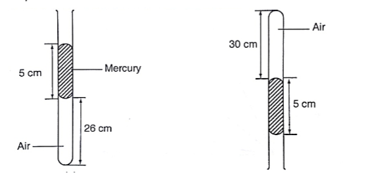
SolutionBefore inversion, gas pressure = atm. Pressure + h p g
After inversion, gas pressure = atm. Pressure – h p g
From Boyle’s law, P1 V1 = P2 V2, then let the atm. Pressure be ‘x’,
So (x + 5) 0.26 = (x – 5) 0.30
0.26x + 1.30 = 0.3x – 1.5, x = 2.8/ 0.04 = 70 cm.
A general gas law
Any two of the three gas laws can be used derive a general gas law as follows,
P1 V1 / T1 = P2 V2 / T2 or
P V / T = constant – equation of state for an ideal gas.
Examples
1. A fixed mass of gas occupies 1.0 × 10⁻³ m3 at a pressure of 75 cmHg. What volume does the gas occupy at 17.0 0C if its pressure is 72 cm of mercury?
Solution
P V / T = constant so V1 = (76 × 1.0 × 10-3 × 290) / 273 ×72 = 1.12 × 10⁻³ m3
2. A mass of 1,200 cm3 of oxygen at 270C and a pressure 1.2 atmosphere is compressed until its volume is 600 cm3 and its pressure is 3.0 atmosphere. What is the Celsius temperature of the gas after compression?
Solution
Since P1 V1 / T1 = P2 V2 / T2, then T2 = (3 × 600 × 300) / 1.2 × 1,200 = 375 K or 102 0C.
Physics Notes Form 4Physics Form Four Notes
Chapter One
Thin Lences
A lens is conventionally defined as a piece of glass which is used to focus or change the direction of a beam of light passing through it.
They are mainly made of glass or plastic. Lens are used in making spectacles, cameras, cinema projectors, microscopes and telescopes.
Types of thin lenses.
A lens which is thicker at its centre than at its edges converges light and is called convex or converging lens.
A lens which is thicker at its edges than at its centre diverges light and is known as concave or diverging lens.
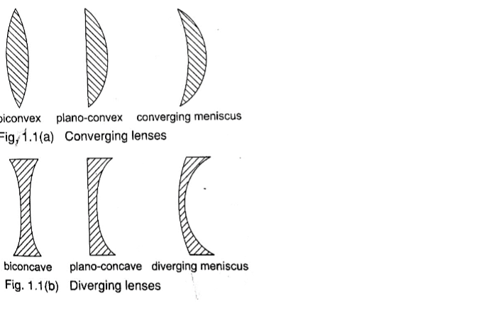
Properties of lenses.1. Optical centre – this is the geometric centre of a lens which is usually shown using a black dot in ray diagrams. A ray travelling through the optical centre passes through in a straight line.
2. Centre of curvature – this is the geometric centre of the circle of which the lens surface is part of. Since lenses have two surfaces there are two centres of curvature. C is used to denote one centre while the other is denoted by C1.
3. Principal axis – this is an imaginary line which passes through the optical centre at right angle to the lens.
4. Principal focus – this is a point through which all rays travelling parallel to the principal axis pass after refraction through the lens.
A lens has a principal focus on both its sides. F is used to denote the principal focus
5. Focal length – this is the distance between the optical centre and the principal focus. It is denoted by ‘f’.
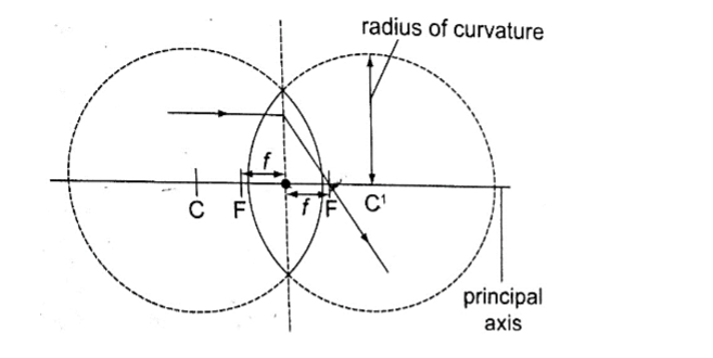
The principal focus for a converging lens is real and virtual for a diverging lens.It is important to note that the principal focus is not always halfway between the optical centre and the centre of curvature as it is in mirrors.
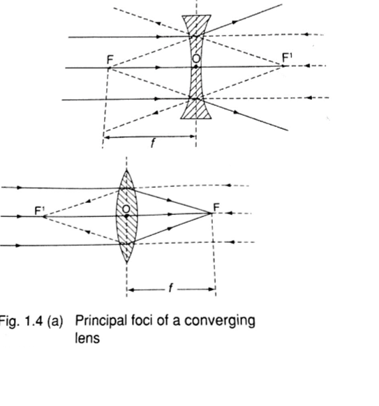
Images formed by thin lenses.The nature, size and position of the image formed by a particular lens depends on the position of the object in relation to the lens.
Construction of ray diagrams
Three rays are of particular importance in the construction of ray diagrams.
1. A ray of light travelling parallel to the principal axis passes through the principal focus on refraction through the lens. In case of a concave lens the ray is diverged in a way that it appears to come from the principal focus.
2. A ray of light travelling through the optical centre goes un-deviated along the same path.
3. A ray of light travelling through the principal focus is refracted parallel to the principal axis on passing through the lens. The construction of the rays is illustrated below.
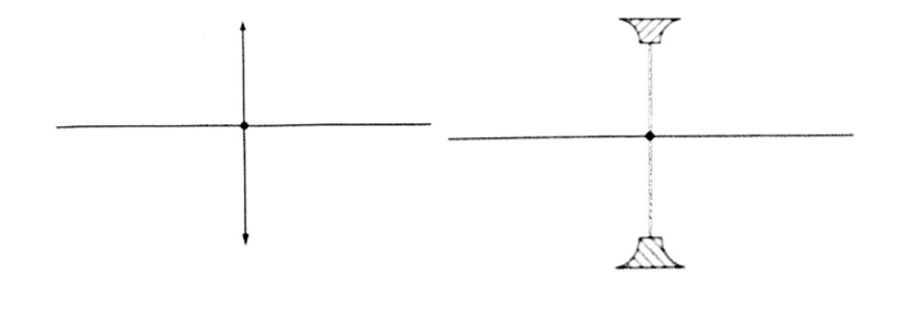
Images formed by a converging lens.1. Object between the lens and the principal focus.
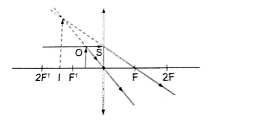
– Image formed behind the object- Virtual
– Erect
– Magnified
2. Object at infinity.
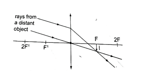
– Image formed at the principal focus of the lens- Real
– Inverted
– Diminished
3. Object at the principal focus (at F).
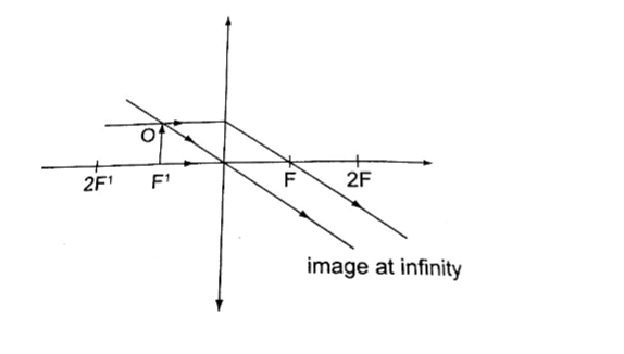
– Image is at infinity.4. Object between the principal focus (F) and 2 F.
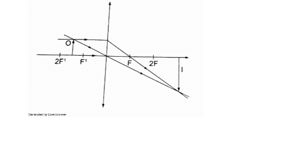
– Image situated beyond 2 F- Real
– Inverted
– Magnified
5. Object at 2 F.
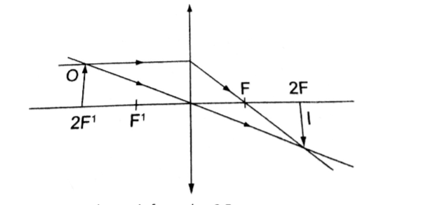
– Image is formed at 2 F- Real
– Inverted
– Same size as the object
6. Object beyond F.
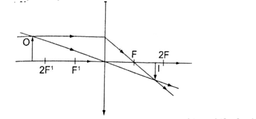
– Image moves nearer to F as object shifts further beyond 2 F- Real
– Inverted
– Diminished
Images formed by a diverging lens.
Images formed by diverging lens are always erect, virtual and diminished for all positions of the object.
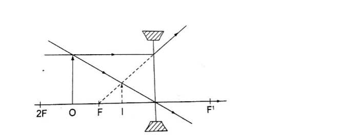
Linear magnification.The linear magnification produced by a lens defined as the ratio of the height of the image to the height of the object, denoted by letter ‘m’, therefore;
m = height of the image / height of the object.
Magnification is also given by = distance of the image from the lens/ dist. of object from lens. m = v / u
Example
An object 0.05 m high is placed 0.15 m in front of a convex lens of focal length 0.1 m.
Find by construction, the position, nature and size of the image. What is the magnification?
Solution
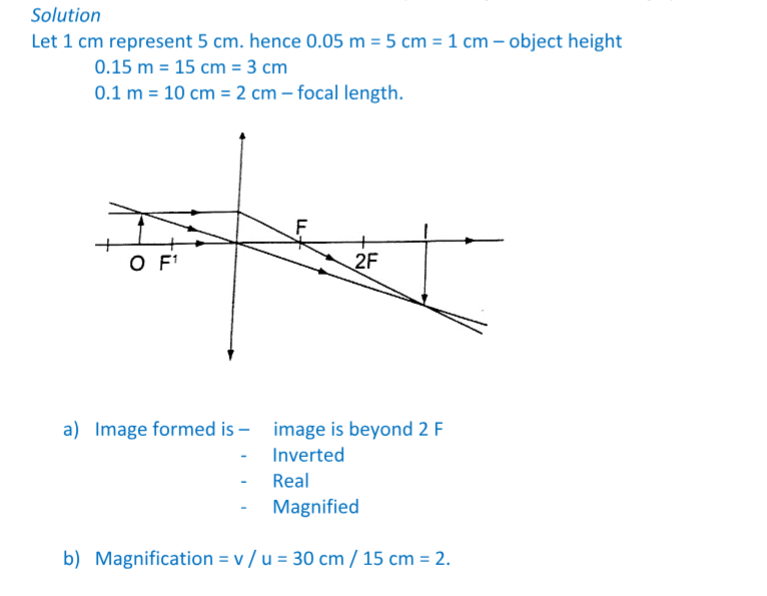
The lens formulaLet the object distance be represented by ‘u’, the image distance by ‘v’ and the focal length by ‘f’, then the general formula relating the three quantities is given by;
1 / f = 1 / u + 1 / v – this is the lens formula.
Examples
1. An object is placed 12 cm from a converging lens of focal length 18 cm. Find the position of the image.
Solution
Since it is a converging lens f = +18 cm (real-is-positive and virtual-is-negative rule)
The object is real therefore u = +12 cm, substituting in the lens formula, then
1 / f = 1 / u + 1 / v or 1 / v = 1 / f – 1 / u = 1 / 18 – 1 / 12 = – 1 / 36
Hence v = – 36 then the image is virtual, erect and same size as the object.
2. The focal length of a converging lens is found to be 10 cm. How far should the lens be placed from an illuminated object to obtain an image which is magnified five times on the screen?
Solution
f = + 10 cm m = v / u = 5 hence v = 5 u
Using the lens formula 1 / f = 1 / u + 1 / v => 1 /10 = 1 / u + 1 / 5 u (replacing v with 5 u)
1 / 10 = 6 / 5 u, hence 5 u = 60 giving u = 12 cm (the lens should be placed 12 cm from the illuminated object)
3. The lens of a slide projector focuses on an image of height 1.5m on a screen placed 9.0 m from the projector.
If the height of the picture on the slide was 6.5 cm, determine, a) Distance from the slide (picture) to the lens
b) Focal length of the lens
Solution
Magnification = height of the image / height of the object = v / u = 150 / 6.5 = 900 / u
u = 39 cm (distance from slide to the lens). m = 23.09
1 / f = 1 / u + 1 / v = 1 /39 + 1 / 90 = 0.02564 + 0.00111
1 / f = 0.02675 (reciprocal tables)
f = 37.4 cm.
Determining focal lengths.
1. Determining focal length of a converging lens
Experiment: To determine the focal length of a converging lens using the lens formula.
Procedure.
1. Set up the apparatus as shown below
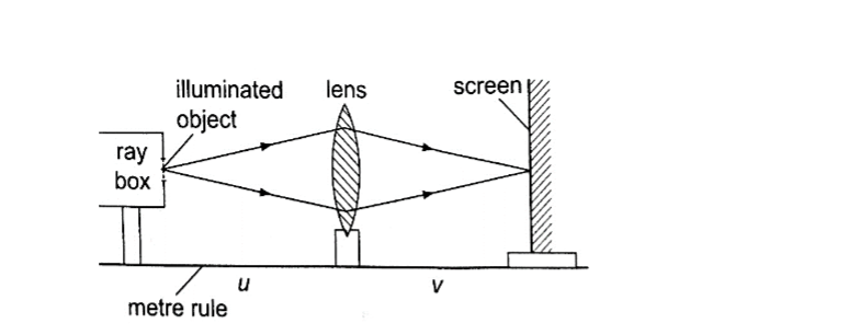
2. Place the object at reasonable length from the screen until a real image is formed on the screen. Move the lens along the metre rule until a sharply focused image is obtained.3. By changing the position of the object obtain several pairs of value of u and v and record your results as shown.
DiscussionThe value u v / u + v is the focal length of the lens and the different sets of values give the average value of ‘f’.
Alternatively the value ‘f’ may be obtained by plotting a graph of 1 / v against 1 / u. When plotted the following graph is obtained.
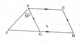
Since 1 / f = 1 / u + 1 / v, at the y-intercept 1 / u = 0, so that 1/ f = 1 / v or f = v. The focal length may therefore be obtained by reading off the y-intercept and finding the reciprocal.Similarly at the x-intercept, 1 / v = 0, therefore 1 / f = 1 / u or f = u hence the focal length can also be obtained by reading off the x-intercept and finding the reciprocal.
Uses of lenses on optical devices
1. Simple microscope – it is also referred to as magnifying glass where the image appears clearest at about 25 cm from the eye.
This distance is known as the least distance of distinct vision (D) or near vision.
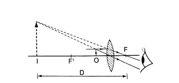
Magnification in a simple microscopeMagnification produced depends on the focal length of the lens. Lens of short focal give greater magnification than those of long focal length.
The angle ϐ subtended by the image at the eye is much greater than α which is the angle that the object would subtend at the eye when viewed without the lens.
The ratio of the ϐ toα is known as angular magnification or magnifying power of an instrument. The angular magnification is equal to linear magnification.
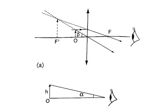
Uses of a simple microscope1. To study the features of small animals in biology
2. To look closely at small print on a map
3. To observe crystals in physics and chemistry
4. For forensic investigation by the police
2. Compound microscope – It consists of two lenses with one nearer the object called the objective lens and the other nearer the eye called the eyepiece lens.
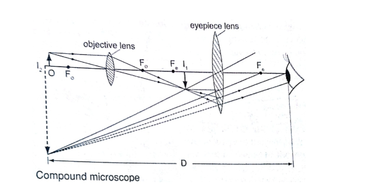
Uses of compound microscope1. Used to observe Brownian motion in science
2. To study micro-organisms and cells in biology
3. Analyze laboratory tests in hospital.
4. The astronomical telescope –It is used to view distant stars. It consists of two lenses; objective and eye-piece lenses. The objective lens has a large focal length while the eye-piece lens has a much shorter focal length.
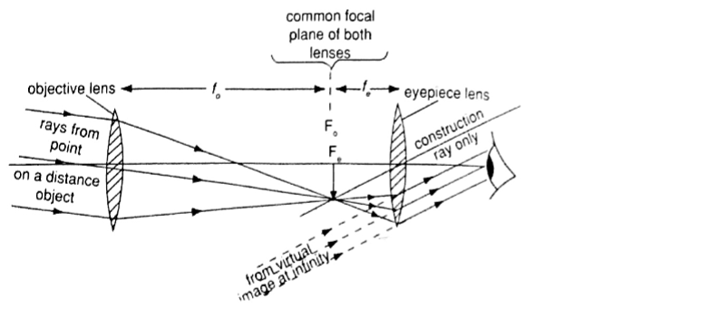
5. The camera – consists of a converging lens system, clicking button, shutter, diaphragm and a mounting base for the film all enclosed in a light proof box.The distance is adjusted to obtain a clear focus.
The diaphragm has a hole called the aperture with an adjusting control knob to control the amount of light entering the camera. The shutter opens to allow light and close at a given time interval.
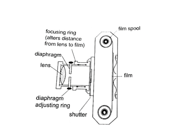
Uses of a camera1. The sine camera is used to make motion pictures
2. High speed cameras are used to record movement of particles
3. Close circuit television cameras (CCTV) are used to protect high security installations like banks, supermarkets etc.
4. Digital cameras are used to capture data that can be fed to computers.
5. Human eye – It consists of a transparent cornea, aqueous humour and a crystal-like lens which form a converging lens system. The ciliary muscles contract or relax to change the curvature of the lens.
Though the image formed at the retina is inverted the brain ‘sees’ the image as upright.
For distant objects ciliary muscles relax while near objects it contracts to control the focal length and this is known as accommodation. When at 25 cmaway an object appears clearest and this is known as least distance of vision or near point.
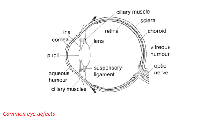
Common eye defects1. Short sightedness or hypermetropia– the eyeball is too large for the ‘relaxed focal length’ of the eye. The defect is corrected by placing a concave lens in front of the eye.
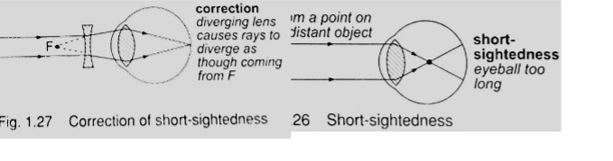
2. Long sightedness or myopia – images are formed beyond the retina. The defect is corrected by placing a converging lens in front of the eye.
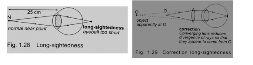
3. Presbyopia – this is the inability of the eye to accommodate and this occurs as the eye ages due to the weakening of the ciliary muscles. It can be corrected by the use a pair of spectacles.4. Astigmatism – this is a defect where the eye has two different focal lengths as a result of the cornea not being spherical. Corrected by the use of cylindrical lens.
5. Colour blindness– caused by deficiency of colour detecting cells in the retina.
Power of lens
The power of a simple lens is given by the formula: Power = 1 / f. The unit for power of a lens is diopter (D).
Example
Find the power of a concave lens of a focal length 25 cm.
Solution
Power = 1 / f = 1 / -0.25 = -4 D.
Chapter Two
Uniform Circular Motion
Introduction
Circular motion is the motion of bodies travelling in circular paths. Uniform circular motion occurs when the speed of a body moving in a circular path is constant. This can be defined as motion of an object at a constant speed along a curved path of constant radius. When acceleration (variation of velocities) is directed towards the centre of the path of motion it is known as centripetal acceleration and the force producing this centripetal acceleration which is also directed towards the centre of the path is called centripetal force.
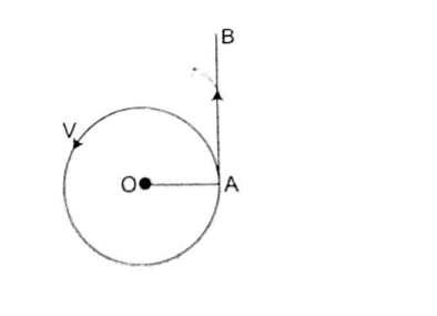
Angular motionThis motion can be described as the motion of a body moving along a circular path by giving the angle covered in a certain time along the path of motion.
The angle covered in a certain time is proportional to the distance covered along the path of motion.
The radian
One radian is the angle subtended at the centre of the circle by an arc of length equal to the radius of the circle. Since one circle = 3600and has 2 π radians therefore 1 radian = 3600 / 2 π r= 57.2960 or 57.30.
Example
A wheel of radius 50 cm is rolled through a quarter turn. Calculate
(i) The angle rotated in radians
(ii) The distance moved by a point on the circumference.
Solution
(i) A quarter turn = 3600 / 4= 900. Since 3600 = 2 π radians.
Alternately since 1 radian = 57.30 hence 900 = 1.57 radii.
(ii) A point on the circumference moves through an arc,
Arc = radius ×θ (θ in radians)
= 50 cm × 1.57
= 78.5 cm.
Angular velocity
If a body moving in a circular path turns through an angle θ radians in time ‘t’, we define angular velocity omega (ω), as the rate of change of the angle θ with time.
ω= θ / t, unit for angular velocity is radians per second (rads-1).
Since the radian measure is a ratio we can write it as second-1 (s-1). We can establish the relationship between angular velocity ‘ω’ and linear velocity ‘v’, from the relation, θ = arc / radius, arc = radius × θ.Dividing the expression by ‘t’, then arc / t = radius, but arc / t = v (angular velocity). So ‘v’ = radius × ω. This expression gives us the relationship between angular and linear velocity.
Angular acceleration
If the angular velocity for a body changes from ‘ω1’ to ‘ω2’, in time ‘t’ then the angular acceleration, α can be expressed as;
α= (ω2 – ω1) / t
Units for angular acceleration are radians per second squared (rad s-2) or second-2 (s-2). When α is constant with time, we say the body is moving with uniform angular acceleration. Note: In uniform circular motion α is equal to zero.
To establish the relationship between angular acceleration and linear acceleration, from the relation, v = radius × ω, then dividing by ‘t’, we get (v / t) = radius × ω / t. But v / t = a (linear acceleration) and ω / t = α (angular acceleration). So a = radius × α.
Centripetal force.
This is a force which acts on a body by directing the body towards its centre. Since the direction is continuously changing, the velocity therefore cannot be constant.
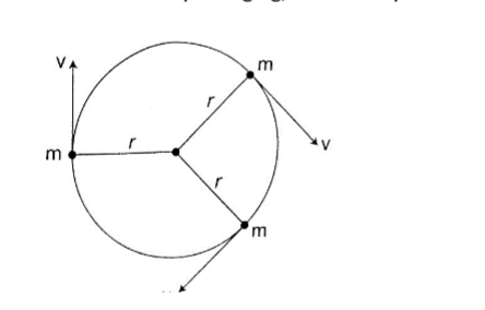
Applying Newton’s law of motion (F = ma), the centripetal force Fc is given by;Fc = ma = mv2/R. Since v = radius ω, then
Fc = mv2 – ω2/R = mRω2.
The centripetal acceleration ‘a’ in relation to angular velocity, ω, is given by a = Rω2.
Motion in a vertical circle
Consider a mass ‘m’ tied to a string of length ‘r’ and moving in a vertical circle as shown below.
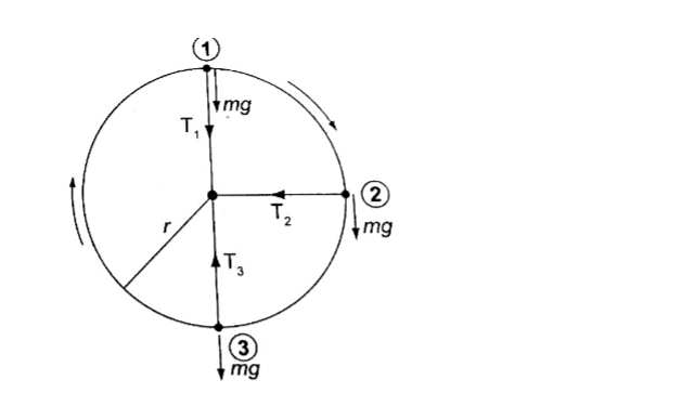
At position 1– both weight (mg) and tension T are in the same direction and the centripetal force is provided by both, hence T1 + mg = mv2/r.T1 = mv2/r – mg.(The velocity decreases as T1decreases since mg is constant).
T1will be zero when mv2/r = mg and thus v = – this is the value of minimum speed at position 1 which keeps the body in a circle and at this time when T = 0 the string begins to slacken.
At position 2 – the ‘mg’ has no component towards the centre thus playing no part in providing the centripetal force but is provided by the string alone.
T2 = mv2/r
At position 3 – ‘mg’ and T are in opposite directions, therefore; T3 – mg = mv2/r; T3 = mv2/r + mg– indicates that the greatest value of tension is at T3 or at the bottom of the circular path.
Examples
1. A ball of mass 2.5 × 10⁻² kg is tied to a string and whirled in a horizontal circular path at a speed of 5.0 ms-2. If the string is 2.0 m long, what centripetal force does the string exert on the ball?
Solution
Fc = mv2/r = (2.5 × 10-2) × 52 / 2.0 = 0.31 N.
2. A car of mass 6.0 × 10³ kg is driven around a horizontal curve of radius 250 m.
if the force of friction between the tyres and the road is 21,000 N. What is the maximum speed that the car can be driven at on a bend without going off the road?
Solution
Fc = force of friction = 21,000, also Fc = mv2/r, hence
21,000 = (6.0 × 10³) × v2 / 250, v2 = (21,000 × 250) /6.0 × 103
3. A stone attached to one end of a string is whirled in space in in a vertical plane. If the length of the string is 80 cm, determine the minimum speed at which the stone will describe a vertical circle. (Take g = 10 m/s2).
Solution
Minimum speed v √rg=0.08× 10 = 2.283 m/s.
The conical pendulum
It consists of a small massive object tied to the end of a thin string tied to affixed rigid support. The object is then pulled at an angle then made to whirl in a horizontal circle.
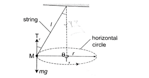
When speed of the object is constant the angle θ becomes constant also. If the speed is increased theangle θ increases, that is the object rises and describes a circle of bigger radius. Therefore as the angular velocity increases ‘r’ also increases.The centrifuge
It consists of a small metal container tubes which can be electrically or manually rotated in a circle. If we consider two particles of different masses m1and m2 each of them requires a centripetal force to keep it in circular motion, the more massive particle require a greater force and so a greater radius and therefore it moves to the bottom of the tube.
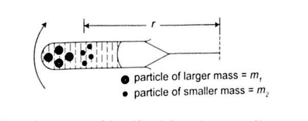
This method is used to separate solids and liquids faster than using a filter paper.Banked tracks
As a vehicle moves round a bend, the centripetal force is provided by the sideways friction between the tyres and the surface, that is;
Centripetal force = mv2/r = frictional force
To enable a vehicle to turn along a bend at high speed the road is raised on the outer edge to attain a saucer-like shape and this is known as banking, where part of the centripetal force necessary to keep the vehicle on track is provided by the weight of the vehicle.
This allows cars to negotiate bends at critical speeds.
Application of uniform circular motion
1. Centrifuges – they are used to separate liquids of different densities i.e. cream and milk
2. Drying clothes in spin dryer– clothes are placed in a perforated drum rotated at high speed, water is expelled through the holes and this makes the clothes dry.
3. Road banking– especially for racing cars which enables them to move at critical speed along bends without going off the tracks.
4. Speed governor– the principle of conical pendulum is used here to regulate the speed by controlling the fuel intake in the combustion chamber.
As the collar moves up and down through a system of levers it thereby connects to a device which controls the fuel intake.
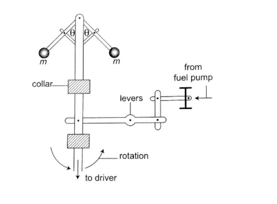
Chapter ThreeFloating and Sinking
Any object in a liquid whether floating or submerged experiences an upward force from the liquid; the force is known as upthrust force.
Upthrust force is also known as buoyant force and is denoted by letter ‘u’.
Archimedes’ principle
Floating and Sinking
Archimedes, a Greek scientist carried out first experiments to measure upthrust on an object in liquid in the third century. Archimedes principle states that ‘When a body is wholly or partially immersed in a fluid (liquid/ gas), it experiences an upthrust equal to the weight of the displaced fluid”.
Floating and Sinking
Experiment: To demonstrate Archimedes principle
Procedure
1. Pour water into an overflow can (eureka can) until it starts to flow out then wait until it stops dripping
2. Tie a suitable solid body securely and suspend it on a spring balance. Determine weight in air.
3. Lower the body slowly into the overflow can while still attached to the spring balance then read off its weight when fully submerged.
4. Weigh the displaced water collected in a beaker.
Record your readings as follows;
Weight of body in air = W1
Weight of body in water = W2
Weight of empty beaker = W3
Weight of beaker and displaced liquid = W4
Upthrust of the body = W1 – W2
Weight of displaced water = W4 – W3
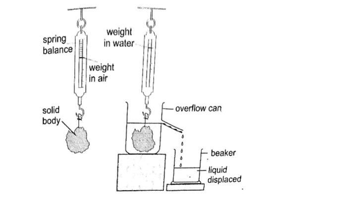
DiscussionThe upthrust on the solid body will be found to be equal to the weight of displaced water therefore demonstrating the Archimedes principle.
Example
A block of metal of volume 60 cm3 weighs 4.80 N in air. Determine its weight when fully submerged in a liquid of density 1,200 kgm-3.
Solution
Volume of liquid displaced = 60 cm3 = 6.0 × 10⁻⁵ m3. Weight of the displaced liquid = volume × density × gravity = v × ρ × g
= 6.0 × 10-5 × 1200 × 10
= 0.72 N
Upthrust = weight of the liquid displaced.
Weight of the block in the liquid = (4.80 – 0.72) = 4.08 N.
Floating objects
Objects that float in a liquid are less dense than the liquid in which they float.
We have to determine the relationship between the weight of the displaced liquid and the weight of the body.
Experiment: to demonstrate the law of floatation
Procedure
1. Weigh the block in air and record its weight as W1.
2. Put water into the overflow can (eureka can) up to the level of the spout.
3. Collect displaced water in a beaker. Record the weight of the beaker first in air and record as W2. Weigh both the beaker and the displaced water and record as W3.
4. Record the same procedure with kerosene and record your results as shown below.
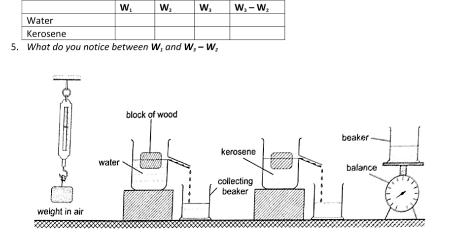
DiscussionThe weight of the displaced liquid is equal to the weight of the block in air.
This is consistent with the law of floatation which states that “A body displaces its own weight of the liquid in which it floats”.
Mathematically, the following relation can be deduced Weight = volume × density × gravity = v × ρ × g, therefore W = v d × ρ × gwhere vdis the volume of displaced liquid.
NOTE – Floatation is a special case of Archimedes principle.
This is because a floating body sinks until the upthrust equals the weight of the body.
Example
A wooden block of dimensions 3 cm × 3 cm × 4 cm floats vertically in methylated spirit with 4 cm of its length in the spirit.
Calculate the weight of the block. (Density of methylated spirit = 8.0 × 10² kgm-3).
Solution
Volume of the spirit displaced = (3 × 3 × 4) = 36 cm3 = 3.6 × 10⁻⁵ m3
Weight of the block =v d × ρ × g = (3.6 × 10-5) × 8.0 × 102 × 10 = 2.88 × 10⁻¹ N.
Relative density
We have established the relative density as the ratio of the density of a substance to the density of water. Since by the law of floatation an object displaces a fluid equal to its own weight hence the following mathematical expressions can be established.
Relative density = density of substance / density of water.
= weight of substance / weight of equal volume of water
= mass of substance / mass of equal volume of water
Applying Archimedes principle, the relative density‘d’;
d = weight of substance in air / upthrust in water or d = W / u
Since upthrust is given by (W2 – W1)where W2 – weight in air, W2– weight when submerged. Hence d = W / u = W / W2 – W1, the actual density, ρ of an object can be obtained as follows ρ of an object = d × 1,000 kgm-3.
Relative density of a floating body
Experiment: To determine the relative density of a cork
Procedure
1. Select a sinker which is heavy enough to make the cork to sink.
2. Attach the cork and the sinker as follows.
3. Record the results obtained as follows
Weight of the sinker in water = W1
Weight of the sinker in water and cork in air = W2
Weight of the sinker and cork in water = W3
Weight of the cork in air = W2 – W1
Upthrust on the cork = W2 – W3
The relative density of the cork in air is determined as follows;
d = weight of the cork in air / upthrust on the cork.
Applications of Archimedes principle and relative density
1. Ships – steel which is used to make ships is 6-7 times dense than water but a ship is able to float on water because it is designed to displace more water than its volume.
Load lines called plimsoll marks are marked on the side to indicate the maximum load at different seasons to avoid overloading.
2. Submarines – they are made of steel and consists of ballast tanks which contain water when they have to sink and filled with air when they have to float.
This makes the submarines to balance their weight and be able to rise upwards.
3. Balloons – when they are filled with helium gas balloons become lighter and the upthrust on the balloon becomes greater than their weight therefore becoming able to rise upwards.
4. Hydrometers – they are used to measure the relative densities of liquids quickly and conveniently. Various types of hydrometers are made to measure different ranges of different densities i.e. lactometer – for measuring milk water (range 1.015 – 1.045), battery acid tester – used to test the charge in a lead-acid battery.
Examples
1. A solid of mass 1.0 kg is suspended using a thread and then submerged in water.
If the tension on the thread is 5.0 N, determine the relative density of the solid.
Solution
Mass of solid = 1.0 kg
Weight of solid W = mg = 10 N
Tension on the string (T) = 5 N
Upthrust on solid (u) = W – T = 10 – 5 = 5
Relative density (d) = W / u = 10 / 5 = 2.
2. A balloon made up of a fabric weighing 80 N has a volume of 1.0 × 107 cm. the balloon is filled with hydrogen of density 0.9 kgm-3.
Calculate the greatest weight in addition to that of the hydrogen and the fabric, which the balloon can carry in air of average density 1.25 kgm-3.
Solution
Upthrust = weight of the air displaced
= volume of air × density × gravity
= (1.0 × 107 × 106) × (1.25 × 10)
= 10 × 1.25 × 10 = 125 N
Weight of hydrogen = 10 × 0.09 × 10 = 9 N
Total weight of hydrogen and fabric = 80 + 9 = 89 N
Total additional weight to be lifted = 125 – 89 = 36 N.
3. A material of density 8.5 gcm-3 is attached to a piece of wood of mass 100g and density 0.2 gcm-3.
Calculate the volume of material X which must be attached to the piece of wood so that the two just submerge beneath a liquid of density 1.2 gcm-3.
Solution
Let the volume of the material be V cm3
The mass of the material be 8.5 V grams
Volume of wood = 100 g / 0.2 g/cm = 500 cm3.
In order to have an average density of 1.2 gcm-3 = total mass / total volume
Therefore (100 + 8.5V) / (500 + V) = 1.2 gcm-3
Hence V = 68.5 cm3.
Electromagnetic Spectrum
Electromagnetic spectrum is a continuum of all electromagnetic waves arranged according to frequency and wavelength.
It includes visible light, ultra-violet rays, microwaves, X-rays, radio waves and gamma rays.
Electromagnetic waves are produced when electrically charged particles oscillate or change energy in some way. The waves travel perpendicularly to both electric and magnetic fields.
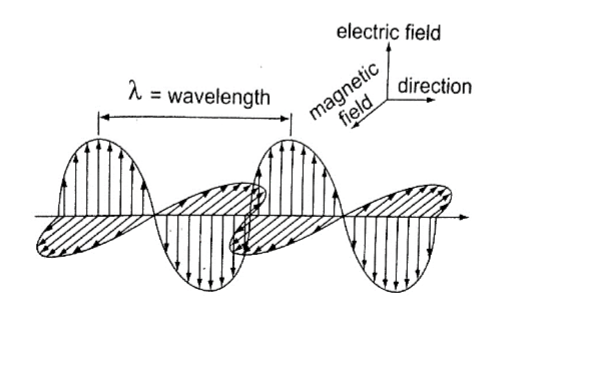
Wavelength, frequency and energy of electromagnetic waves.X-rays and gamma rays are usually described in terms of wavelength and radio waves in terms of frequency.
The electromagnetic spectrum
It is divided into seven major regions or bands. A band consists of a range of frequencies in the spectrum in terms of frequencies i.e. radio, microwaves, infra-red.
Properties of electromagnetic waves
Common properties
i. They do not require a material medium and can travel through a vacuum.
ii. They undergo reflection, refraction and diffraction.
iii. All electromagnetic waves travel at the speed of light i.e. 3 × 10⁸ ms-1.
iv. They carry no electric charge
v. They transfer energy from a source to a receiver in the form of oscillating electric and magnetic fields.
vi. They obey the wave equation (v = λ f).
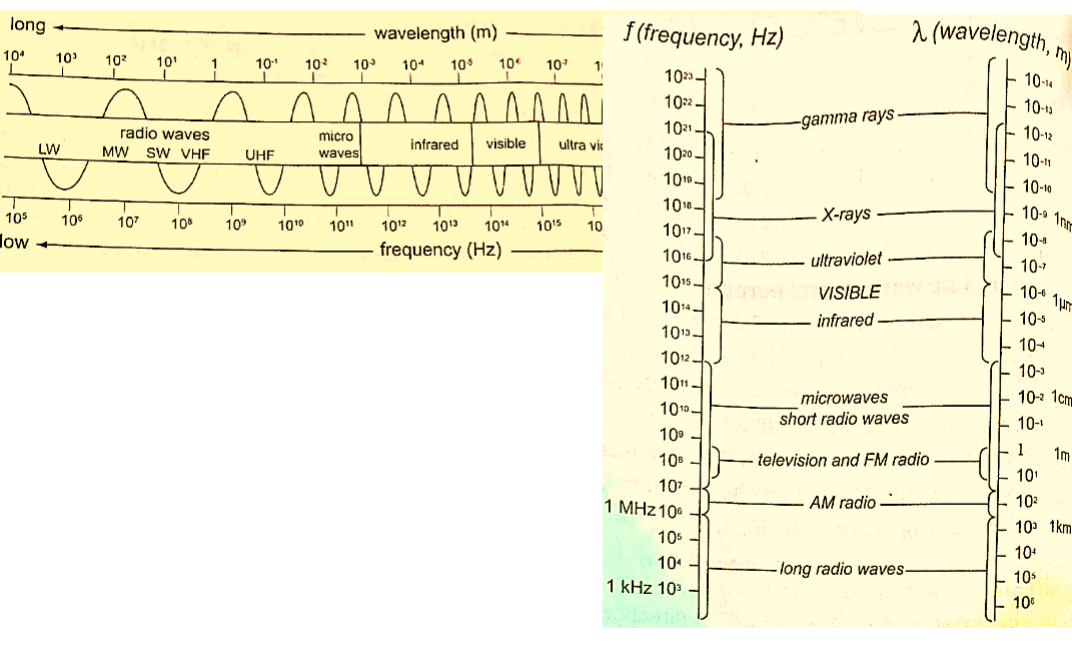
Examples1. A VHF radio transmitter broadcasts radio waves at a frequency of 30 M Hz. What is their wavelength?
Solution
v = f λ => then λ = v / f = 3.0 × 10⁸ / 300 × 106 = 1.00 m.
2. Calculate the frequency of a radio wave of wavelength 150 m.
Solution
v = f λ =>f = v / λ = 2.0 × 106 = 2 M Hz.
Unique properties
1. Radio waves – they are further divided into long waves (LW), medium waves (MW) and short waves (SW).
They are produced by electrical circuits called oscillators and they can be controlled accurately.
They are easily diffracted by small objects like houses but not by large objects like hills.
2. Microwaves – they are produced by oscillation of charges in special aerials mounted on dishes. They are detected by special receivers which convert wave energy to sound i.e. ‘RADAR’ – Radio Detection and Raging.
3. Infra-red radiation – infra-red radiations close to microwaves are thermal (produce heat) i.e. sun, fire but those closer to the visible light have no thermal properties i.e. TV remote control system. Detectors of infra-red radiation are the human skin, photographic film etc.
4. Optical spectrum (visible light) – they form a tiny part of the electromagnetic spectrum. Sources include the sun, electricity, candles etc. these have wavelengths visible to the human eye and includes the optical spectrum (ROYGBIV). It is detected through the eyes, photographic films and photocells.
5. Ultra-violet rays (UV) – has shorter wavelength than visible light. It is emitted by very hotobjects i.e. the sun, welding machines etc. Exposure to UV rays may cause skin cancer and cataracts. They can be detected through photographic film.
6. X-rays – they have very short wavelength but are high energy waves. They are produced in X-ray tubes when high speed electrons are stopped by a metallic object. They are detected by the use of a photographic film or a fluorescent screen.
7. Gamma rays – produced by some radioactive materials when large changes of energy occur inside their nuclei.
They can be detected by the use of photographic films, Geiger Muller tube or a cloud chamber.
Applications of electromagnetic radiation
1. Radio waves – they are used in radio, TV and cellular mobile communications. -Used in military communications (satellite imagery) to form an image of the ground even when there are clouds.
2. Microwaves – used in radar communications by giving direction and distance.
-Used in speed guns by the police to detect over speeding.
-Used in microwave ovens to warm food. The food becomes warm by absorbing energy.
-Used reliably for communication (telephone and computer data).
3. Infra-red radiation – used to produce images of hot objects through the colours
-Produced by the amount of heat dissipated by an object.
-Images produced by satellites give important information on vegetation cover in all areas of the globe. They can also detect fires.
-They are used in hospitals to detect illnesses (diagnosis)
-Used in warfare missiles and burglar alarm systems
-Used in green houses to grow crops
4. Visible light – used by plants in remote sensing and humans in the identification of things
-Used by plants in the process of photosynthesis
5. Ultra-violet (UV) radiation – used to make reflective materials which absorb light and re-emit it as visible light.
-Used in banks to detect fake currency
6. X-rays – used in hospitals to detect fractures, broken bones and in treatment of cancer (radiotherapy).
-Used to detect foreign materials in the body i.e. metals
-Used to detect invisible cracks in metal castings and welding joints
7. Gamma rays – used to sterilize medical instruments -Used to kill weevils in grain
-Used to take photographs same way like X-rays.
Chapter Five
Electromagnetic Induction
Electromagnetism is the effect resulting from the interaction between an electric current and a magnetic field. This effect brings about induced electromagnetic force (e.m.f) and the resulting current is called induced current.
Experiments on electromagnetic induction
Consider the following diagram
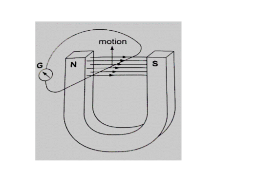
When the wire is moved up the galvanometer deflects in one direction then the opposite direction when moved downwards.When moved horizontally or held in a fixed position there is no deflection in the galvanometer.
This shows that e.m.f is induced due to the relative motion of the wire or the magnet.
Factors affecting the magnitude of the induced e.m.f
1. The rate of relative motion between the conductor and the field – if the velocity of the conductor is increased the deflection in the conductor increases.
2. The strength of the magnetic field – a stronger magnetic field creates a bigger deflection
3. The length of the conductor – if the length is increased in the magnetic field the deflection increases.
Faraday’s law of magnetic induction
After considering the factors affecting the magnitude of the induced e.m.f, Michael Faraday came up with a law which states that “The induced e.m.f in a conductor in a magnetic field is proportional to the rate of change of the magnetic flux linking the conductor”.
Lenz’s law of electromagnetic induction
This law is used to determine the direction of the induced current in a conductor. It states that “An induced current flows in such a direction that its magnetic effect opposes the change through which the current has been produced”.
It is applied similarly when a wire is been moved in magnetic field.
Fleming’s right hand rule.
The law states that “The first finger, the second finger and the thumb of the right hand when placed mutually perpendicular to each other, the first finger points in the direction of the field and the thumb in the direction of motion then second finger points in the direction of the induced current”. This law is also called the generator rule.
Applications of electromagnetic induction1. A.c generator/alternator – a generator is a device which produces electricity on the basis of electromagnetic induction by continuous motion of either a solenoid or a magnet.
It consists of an armature made of several turns of insulated wire wound on soft iron core and revolving freely on an axis between the poles of a powerful magnet.
Two slip rings are connected to the ends of the armature with two carbon brushes rotating on the slip ring.
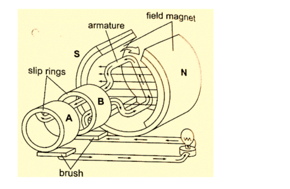
In an external circuit the current is at maximum value at 900 and minimum value at2700.This brings about alternating current and the corresponding voltage (e.m.f) is the alternating voltage. They are used in car alternators and H.E.P.
2. D.c generator/alternator – in this case the commutators replaces the slip rings to enable the output to move in one direction.
After a rotation of 1800, instead of current reversing, the connections to the external circuit are reversed so that current direction flows in one direction.
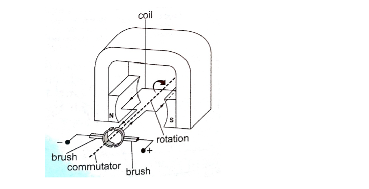
3. Moving coil microphone – it consists of a coil wound on a cylindrical cardboard which opens into a diaphragm. The coil is placed between the poles of a magnet as shown.
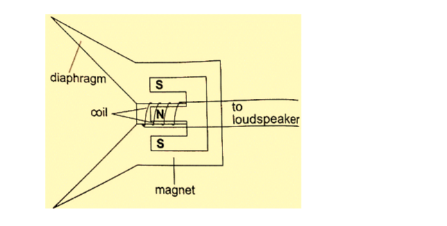
As sound waves hit the diaphragm, they vibrate and move the coil which produces induced current into the coil and then it flows to the loudspeakers.Eddy currents
They are composed of loops of current which have a magnetic effect opposing the force producing them.
When a copper plate with slits is used the loops are cut off and hence the effective currents are drastically reduced and so is the opposing force.
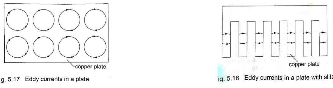
Practically eddy currents are reduced by laminating metal plates. Armatures of electric generators and motors are wound on laminated soft iron cores.The lamination slices, which are quite thin are glued together by a non-conducting glue and this reduces eddy currents to an almost negligible value.
Eddy currents are useful in moving coil meters to damp the oscillations of the armature when the current is switched off.
Mutual induction
Mutual induction is produced when two coils are placed close to each other and a changing current is passed through one of them which in turn produces an induced e.m.f in the second coil. Therefore mutual induction occurs when a changing magnetic flux in one coil links to another coil.
Applications of mutual induction
1. The transformer – it converts an alternating voltage across one coil to a larger or smaller alternating voltage across the other. Since H.E.P is lost through transmission lines therefore it is stepped down before it being transmitted and stepped up again at the point of supply lines.
In a step up transformer the number of turns in the secondary coil (Ns) is higher than the number of turns in the primary coil (Np).
In a step down transformer the primary coil has more turns than the secondary coil.
The relationship between the primary voltage and the secondary voltage is given by;
Np / Ns = Vp / Vs.The efficiency of a transformer is the ratio of power in secondary coil (Ps) to power in primary coil (Pp), therefore efficiency = Ps / Pp × 100%.
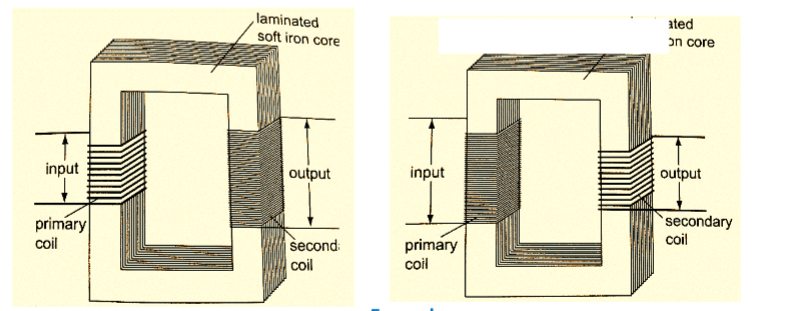
Examples1. A current of 0.6 A is passed through a step up transformer with a primary coil of 200 turns and a current of 0.1 A is obtained in the secondary coil. Determine the number of turns in the secondary coil and the voltage across if the primary coil is connected to a 240 V mains.
Solution
Np / Ns = Vp / Vs = Ip / Is = Ns = (0.6 × 200) / 0.1 = 1200 turns
Vp = 240 V hence Vs = (240 × 1200) / 200 = 1440 V
2. A step-up transformer has 10,000 turns in the secondary coil and 100 turns in the primary coil.
An alternating current of 0.5 A flows in the primary circuit when connected to a 12.0 V a.c. supply.
a) Calculate the voltage across the secondary coil
b) If the transformer has an efficiency of 90%, what is the current in the secondary coil?
Solution
a) Vs = (Ns / Np) × Vp = (10,000 × 12) / 100 = 1200 V
b) Power in primary = Pp = Ip × Vp= 5.0 × 12 = 60 W
Efficiency = Ps / Pp × 100% but Ps = Is Vs
Is = (60 × 90) / (1200 × 100) = 0.045 A
Energy losses in a transformer.
Loss of energy in a transformer is caused by;
i) Flux leakage– this may be due to poor transformer design
ii) Resistance in the windings–it is reduced by using copper wires which have very low resistance
iii) Hysteresis losses– caused by the reluctance of the domains to rotate as the magnetic field changes polarity. Reduced by using materials that magnetize and demagnetize easily like soft iron in the core of the transformer.
iv) Eddy currents– reduced by using a core made of thin, well insulated and laminated sections.
Uses of transformers
1. Power stations – used to step up or down to curb power losses during transmission
2. Supplying low voltages for school laboratories
3. Low voltage supply in electronic goods like radios, TVs etc.
4. High voltage supply in cathode ray oscilloscope (CRO) for school laboratories.
3. Induction coil –was developed in 1851 by Heinrich Ruhmkortt. It has both secondary and primary coils with an adjustable spark gap.
4. Car ignition system – it is applied in petrol driven engines where a spark plug is used to ignite petrol vapour and air mixture to run the engine.
Chapter Six
Mains Electricity
Sources of mains electricity
Mains electricity comes from a power station and its current is the alternating current which can either be stepped up or down by a transformer.
A.c is produced when a conductor is rotated in a magnetic field or when a magnetic field is rotated near a conductor.
This method is known as electromagnetic induction. The source of energy for rotating the turbine is the actual source of electrical energy.
Most of the electricity in East Africa is generated from water.
Power transmission
This is the bulk transfer of electric power from one place to another. A power transmission system in a country is referred to as the national grid.
This transmission grid is a network of power generating stations, transmission circuits and sub-stations. It is usually transmitted in three phase alternating current.
Grid input
At the generating plant the power is produced at a relatively low voltage of up to 25 kV then stepped up by the power station transformer up to 400 kV for transmission. It is transmitted by overhead cables at high voltage to minimize energy losses.
The cables are made of aluminium because it is less dense than copper.
Metallic poles (pylons) carry four cables, one for each phase and the fourth is the neutral cable which is thinner and completes the circuit to the generator.
Grid exit
At sub-stations transformers are used to step down voltage to a lower voltage for distribution to industrial and domestic users.
The combination of sub-transmission (33 kV to 132 kV) and distribution (11 kV to 33 kV) which is then finally transformed to a voltage of 240 V for domestic use.
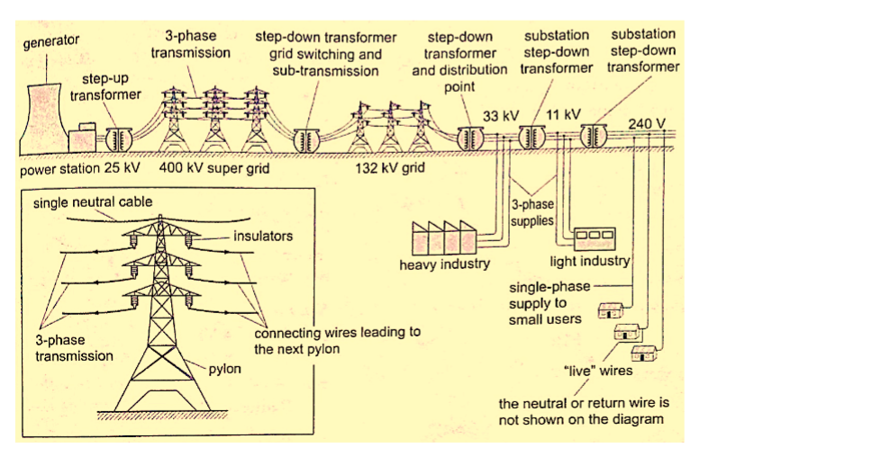
Electricity distributionThis is the penultimate process of delivery of electric power. It is considered to include medium voltage (less than 50 kV) power lines, low voltage (less than 1,000 V) distribution, wiring and sometimes electricity meters.
FREE PHYSICS NOTES FOR FORM ONE TO FOUR.
Download more notes and other teachers’ resources here; Teachers’ Free Resources Portal.
FREE PHYSICS UPDATED NOTES FOR FORM 1-4
FREE PHYSICS UPDATED NOTES FOR FORM 3
FREE PHYSICS UPDATED NOTES FOR FORM 1
FREE PHYSICS UPDATED LESSON NOTES FOR FORM 4
FREE PHYSICS UPDATED LESSON NOTES FOR FORM 3
FREE PHYSICS UPDATED NOTES FOR FORM 1-4
FREE PHYSICS UPDATED COMPLETE NOTES FOR FORM 1-4
FREE PHYSICS UPDATED NOTES FOR FORM 3 SIMPLIFIED
FREE PHYSICS UPDATED NOTES FOR FORM 2
FREE PHYSICS UPDATED NOTES FOR FORM 2 SIMPLIFIED
FREE PHYSICS UPDATED NOTES FOR FORM 1
FREE PHYSICS UPDATED NOTES FOR FORM 2 HANDBOOK
FREE PHYSICS UPDATED NOTES FOR FORM 1 HANDBOOK
FREE PHYSICS UPDATED NOTES FOR PAPER (REVISION)
FREE PHYSICS TOPICAL QUESTIONS WITH ANSWERS
Dangers of high voltage transmission
1. They can lead to death through electrocution
2. They can cause fires during upsurge
3. Electromagnetic radiations from power lines elevate the risk of certain types of cancer
Electrical power and energy
Work done = volts × coulombs = VQ, but Q = current × time = I t.
So work done = V I t
Other expressions for work may be obtained by substituting V and I from Ohms law as below V = I R and I = V / R, work done = I R × I t = I2 R t, or work done = V × V t / R = V2 t / R. The three expressions can be used to calculate work done. Electrical power may be computed from the definition of power. Power = work / time = I2 R t /t = I2 R or V2 t / R t = V2 / R Using work done = V I t, then Power = V I.
These expressions are useful in solving problems in electricity. Work done or electrical energy is measured in joules (J) and power is measured in watts (W). 1 W = 1 J/s.
Example
An electric heater running on 240 V mains has a current of 2.5 A.
a) What is its power rating?
b) What is the resistance of its element?
Solution
a) Power = V I = 240 × 2.5 = 600 W. Rating is 600 W, 240 V.
b) Power = V / R = 600 W. R = V / I. R = 240 / 2.5 = 96 Ω.
Costing electricity
The power company uses a unit called kilowatt hour (kWh) which is the energy transformed by a kW appliance in one hour.
1 kW = 1,000 W × 60 × 60 seconds = 3,600,000 J. The meter used for measuring electrical energy uses the kWh as the unit and is known as joule meter.
Examples
1. An electric kettle is rated at 2,500 W and uses a voltage of 240 V.
a) If electricity costs Ksh 1.10 per kWh, what is the cost of running it for 6 hrs?
b) What would be its rate of dissipating energy if the mains voltage was dropped to 120 V?
Solution
a) Energy transformed in 6 hrs = 2.5 × 6 = 15 kWh. Cost = 15 × 1.10 × 6 = Ksh 99.00 b) Power = V2 / R = 2500. R = (240 × 240) /2500 = 23.04 Ω.
Current = V / R = (240 × 2500) / (240 × 240) = 10.42 A
Power = V I = (2500 × 120) / 240 = 1,250 W.
2. An electric heater is made of a wire of resistance 100 Ω connected to a 240 V mains supply.
Determine the;
a) Power rating of the heater
b) Current flowing in the circuit
c) Time taken for the heater to raise the temperature of 200 g of water from 230C to 950C. (specific heat capacity of water = 4,200 J Kg-1 K-1)
d) Cost of using the heater for two hours a day for 30 days if the power company charges Ksh 5.00 per kWh.
Solution
a) Power = V2 / R = (240 × 240) / 100 = 576 W
b) P = V I =>> I = P / V = 576 / 240 = 2.4 A
c) P × t = heat supplied = (m c θ) = 576 × t = 0.2 × 4200 × 72.
Hence t = (0.2 × 4200 × 72) / 576 = 105 seconds.
d) Cost = kWh × cost per unit = (0.576 × 2 × 30) × 5.0 = Ksh 172.80
3. A house has five rooms each with a 60 W, 240 V bulb. If the bulbs are switched on fro 7.00 pm to 10.30 pm, calculate the;
a) Power consumed per day in kWh
b) Cost per week for lighting those rooms if it costs 90 cents per unit.
Solution
a) Power consumed by 5 bulbs = 60 × 5 = 300 W = 0.3 kWh. Time = 10.30 – 7.00 = 3 ½ hrs.Therefore for the time duration = 0.3 × 3 ½ = 1.05 kWh.
b) Power consumed in 7 days = 1.05 × 7 = 7.35 kWh. Cost = 7.35 × 0.9 = Ksh 6.62
Domestic wiring system
Power is supplied by two cables where one line is live wire (L) and the other is neutral (N). Domestic supply in Kenya is usually of voltage 240 V. The current alternates 50 times per second hence the frequency is 50 Hz.
The neutral is earthed to maintain a zero potential. The main fuse is fitted on the live wire to cut off supply in case of a default. A fuse is a short piece of wire which melts if current of more value flows through it.
Supply to the house is fed to the joule meter which measures the energy consumed.
From the meter both L and N cables go to the consumer box (fuse box) through the main switch which is fitted on the live cable.
Consumer units within the house are fitted with circuit breakers which go off whenever there is a default in the system.
Lights in the house are controlled by a single or double switch (two way).
In most wiring systems the main sockets are connected to a ring main which is a cable which starts and end at the consumer unit. Plugs used are the three- pin type.
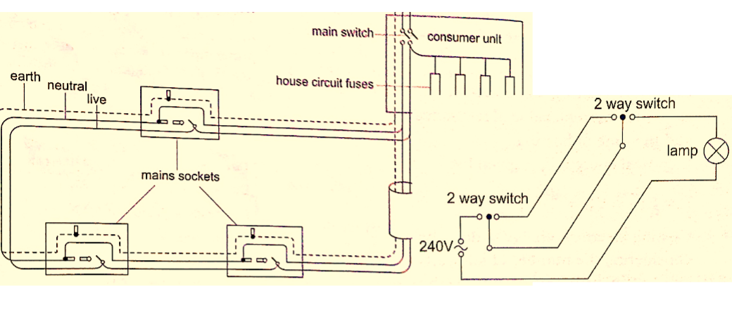
Chapter Seven
Cathode Rays
These are streams of electrons emitted at the cathode of an evacuated tube containing an anode and a cathode.
Production of cathode rays
They are produced by a set up called a discharge tube where a high voltage source usually referred to as extra high tension (EHT) supply connected across a tube containing air at low pressure thereby producing a luminous electron discharge between the two brass rods placed at opposite ends of the tube. These electron discharges are called cathode rays which were discovered by J.J Thomson in the 18th century.
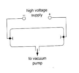
Properties of cathode rays
1. They travel in straight lines
2. They are particulate in nature i.e. negatively charged electrons
3. They are affected by both magnetic and electric fields since they are deflected towards the positive plates
4. They produce fluorescence in some materials
5. Depending on the energy of the cathode rays they can penetrate thin sheets of paper, metal foils
6. When cathode rays are stopped they produce X-rays.
7. They affect photographic plates.
Cathode ray oscilloscope (CRO)
It is a complex equipment used in displaying waveforms from various sources and measuring p.d. It comprises of the following main components; – The cathode ray tubes (CRT) – consists of a tube, electron gun, deflection plates and the time base (TB).
The tube is made of strong glass to withstand the pressure difference between the outside atmospheric pressure and the vacuum inside.
It has a square grid placed in front of it to allow measurements to be made.
The electron gun produces the electrons with main parts consisting of a filament, a cathode, a grid and the anode.
Electrons are produced by the cathode when heated by the filament.
The grid is a control electrode which determines the number of electrons reaching the screen therefore determining the brightness of the screen. The Y-deflection plates deflects the beam up or down.
Clearly observable when low frequency inputs are applied i.e. 10 Hz from a signal operator.
The X-deflection plates are used to move the beam left or right of the screen at a steady speed using the time base circuit which automatically changes voltage to an a.c.
voltage. When time base control is turned the speed can be adjusted to produce a waveform.
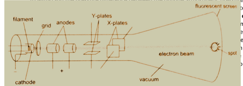
Examples
1. If the time base control of the CRO is set at 10 milliseconds per cm, what is the frequency of the wave traced given wavelength as 1.8 cm?
Solution
Wavelength = 1.8 cm. time for complete wave = period = 1.8 × 10 milliseconds / cm
= 18 milliseconds
= 1.8 × 10⁻² seconds.
Frequency ‘f’, is given by f = 1 / T = 1 / 1.8 × 10-2 = 100 / 1.8 = 56 Hz.
NOTE:
The television set (TV) is a type of a CRT with both Y and X-deflection plates which control the formation of a picture (motion) on the screen.
The colour television screen is coated with different phosphor dots (chemicals) which produce a different colour when struck by an electron beam.
Chapter Eight
X-rays
X-rays were discovered by a German scientist named Roentgen in 1985. They can pass through most substances including soft tissues of the body but not through bones and most metals. They were named X-rays meaning ‘unknown rays’.
X-ray production
They are produced by modified discharge tubes called X-ray tubes. The cathode is in the form of a filament which emits electrons on heating.
The anode is made of solid copper molybdenum and is called the target. A high potential difference between the anode and the cathode is maintained (10,000 v to 1,000,000 or more) by an external source. The filament is made up of tungsten and coiled to provide high resistance to the current.
The electrons produced are changed into x-rays on hitting the anode and getting stopped.
Only 0.2% of the energy is converted into x-rays.
Cooling oil is led in and out of the hollow of the anode to maintain low temperature. The lead shield absorbs stray x-rays.
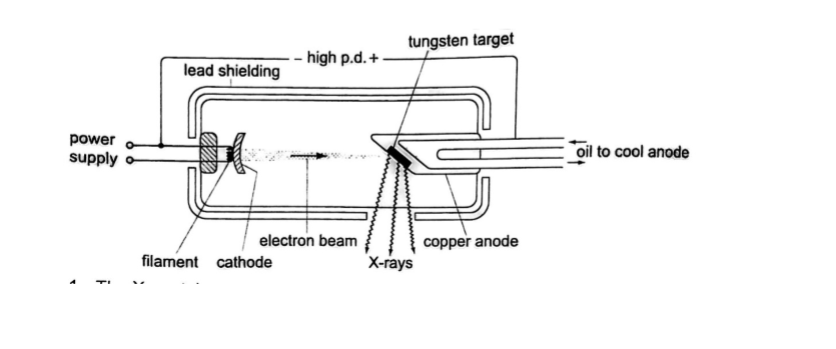
Energy changes in an X-ray tube.
When the cathode is heated electrons are emitted by thermionic emission. They acquire electrical energy which can be expressed as E = e V. Once in motion the electrical energy is converted to kinetic energy, that is eV = ½ me v2.
The energy of an electromagnetic wave can be calculated using the following equation Energy = h f,where h- Planck’s constant, f – frequency of the wave.
The highest frequency of the X-rays released after an electron hits the target is when the greatest kinetic energy is lost, that is h f max = eV.
Lower frequencies are released when the electrons make multiple collisions losing energy in stages, the minimum wavelength, λ min, of the emitted X-rays is given by;
(hc) / λ min = eV.
These expressions can be used to calculate the energy, frequencies and wavelengths of X-rays.
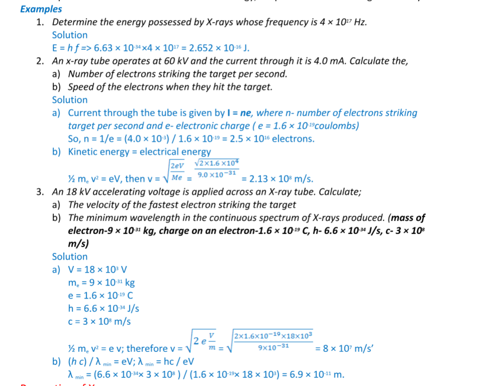
Properties of X-rays
i) They travel in straight lines
ii) They undergo reflection and diffraction
iii) They are not affected by electric or magnetic fields since they are not charged particles.
iv) They ionize gases causing them to conduct electricity
v) They affect photographic films
vi) They are highly penetrating, able to pass easily through thin sheets of paper, metal foils and body tissues
vii) They cause fluorescence in certain substances for example barium platinocynide.
Hard X-rays
These are x-rays on the lower end of their range (10-11 – 10-8 m) and have more penetrating power than normal x-rays.
They are capable of penetrating flesh but are absorbed by bones.
Soft X-rays
They are on the upper end of the range and are less penetrative. They can only penetrate soft flesh and can be used toshow malignant growth in tissues.
Dangers of X-rays and the precautions.
1. They can destroy or damage living cells when over exposed.
2. Excessive exposure of living cells can lead to genetic mutation.
3. As a precautionary measure X-ray tubes are shielded by lead shields.
Uses of X-rays
1. Medicine – X-ray photos called radiographs are used as diagnostic tools for various diseases. They are also used to treat cancer in radiotherapy.
2. Industry – they are used to photograph and reveal hidden flaws i.e. cracks in metal casting and welded joints.
3. Science – since the spacing of atomic arrangement causes diffraction of x-rays then their structure can be studied through a process called X-ray crystallography.
4. Security – used in military and airport installations to detect dangerous metallic objects i.e. guns, explosives, grenades etc.
Chapter Nine
Photoelectric Effect
Photoelectric effect was discovered by Heinrich Hertz in 1887. Photoelectric effect is a phenomenon in which electrons are emitted from the surface of a substance when certain electromagnetic radiation falls on it.
Metal surfaces require ultra-violet radiation while caesium oxide needs a visible light i.e. optical spectrum (sunlight).
Work function
A minimum amount of work is needed to remove an electron from its energy level so as to overcome the forces binding it to the surface.
This work is known as the work function with units of electron volts (eV). One electron volt is the work done when one electron is transferred between points with a potential difference of one volt; that is,
1 eV = 1 electron × 1 volt
1 eV = 1.6 × 10-19 × 1 volt
1 eV = 1.6× 10⁻¹⁹ Joules (J)
Threshold frequency
This is the minimum frequency of the radiation that will cause a photoelectric effect on a certain surface. The higher the work function, the higher the threshold frequency.
Factors affecting the photoelectric effect
1. Intensity of the incident radiation – the rate of emission of photoelectrons is directly proportional to the intensity of incident radiation.
2. Work function of the surface – photoelectrons are emitted at different velocities with the maximum being processed by the ones at the surface.
3. Frequency of the incident radiation – the cut-off potential for each surface is directly proportional to the frequency of the incident radiation.
Planck’s constant
When a bunch of oscillating atoms and the energy of each oscillating atom is quantified i.e. it could only take discrete values.
Max Planck’s predicted the energy of an oscillating atom to be E = n h f, where n – integer, f – frequency of the source, h – Planck’s constant which has a value of 6.63 × 10⁻³⁴ Js.
Quantum theory of light
Planck’s published his quantum hypothesis in 1901 which assumes that the transfer of energy between light radiation and matter occurs in discrete units or packets.
Einstein proposed that light is made up of packets of energy called photons which have no mass but they have momentum and energy given by;
E = h f
The number of photons per unit area of the cross-section of a beam of light is proportional to its intensity. However the energy of a photon is proportional to its frequency and not the intensity of the light.
Einstein’s photoelectric equation
As an electron escapes energy equivalent to the work function ‘Φ’ of the emitter substance is given up. So the photon energy ‘h f’ must be greater than or equal to Φ. If the ‘h f’ is greater than Φ then the electron acquires some kinetic energy after leaving the surface.
The maximum kinetic energy of the ejected photoelectron is given by;
K.E max = ½ m v2max = h f – Φ ……………… (i), where m v2max = maximum velocity and mass.
This is the Einstein’s photoelectric equation.
If the photon energy is just equivalent to work function then, m v2max = 0, at this juncture the electron will not be able to move hence no photoelectric current, giving rise to a condition known as cut-off frequency, h fco = Φ………………. (ii)
Also the p.d required to stop the fastest photoelectron is the cut-off potential, V cowhich is given by E = e V co electron volts, but this energy is the maximum kinetic energy of the photoelectrons and therefore, ½ m v2max = e V co ………….. (iii).
Combining equations (i), (ii) and (iii), we can write Einstein’s photoelectric equation as, e V co = h f – h fco ………………….. (iv)
NOTE: — Equations (i) and (iv) are quite useful in solving problems involving photoelectric effect.
Examples
1. The cut-off wavelength for a certain material is 3.310 × 10⁻⁷ m. What is the cut-off frequency for the material?
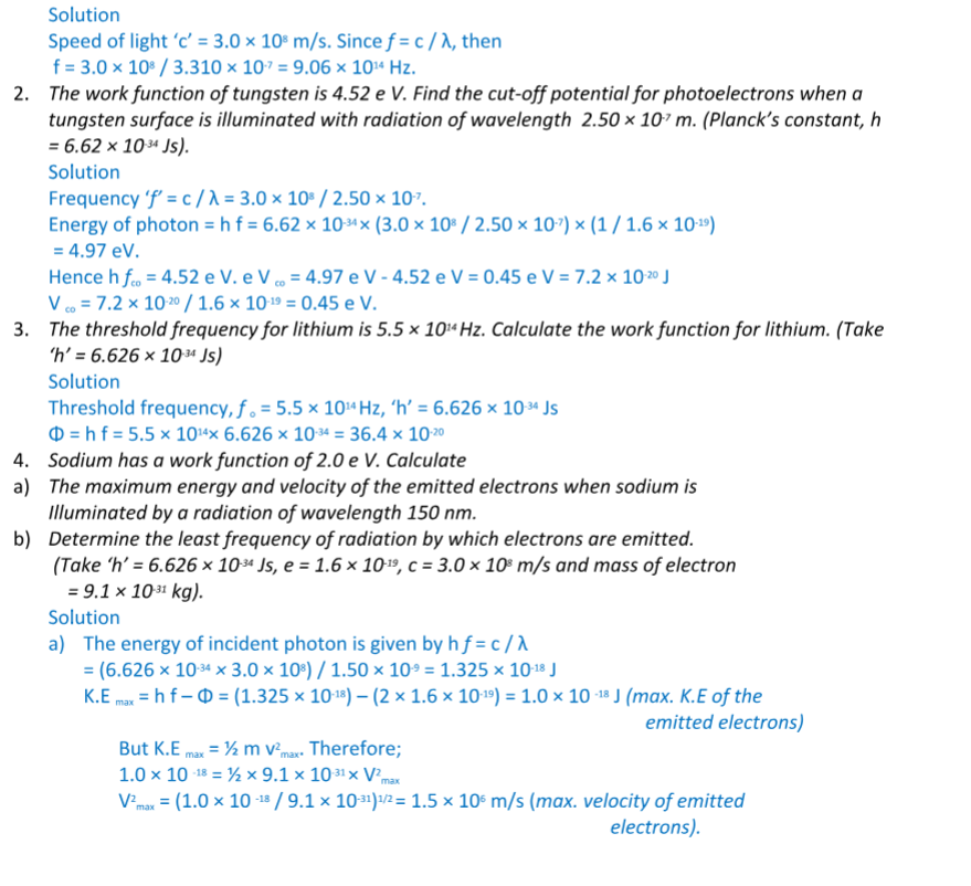
Applications of photoelectric effect
1. Photo-emissive cells – they are made up of two electrodes enclosed in a glass bulb (evacuated or containing inert gas at low temperature).
The cathode is a curved metal plate while the anode is normally a single metal rod)
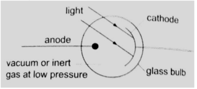
They are used mostly in controlling lifts (doors) and reproducing the sound track in a film. Photoconductive cells – some semi-conductors such as cadmium sulphide (cds) reduces their resistance when light is shone at them (photo resistors).
Other devices such as photo-diodes and photo-transistors block current when the intensity of light increases.
Photo-conductive cells are also known as light dependent resistors (LDR) and are used in alarm circuits i.e. fire alarms, and also in cameras as exposure metres.
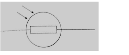
2. Photo-voltaic cell– this cell generates an e.m.f using light and consists of a copper disc oxidized on one surface and a very thin film of gold is deposited over the exposed surfaces (this thin film allows light). The current increases with light intensity.
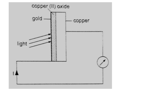
They are used in electronic calculators, solar panels etc.
Chapter Ten
Radioactivity
Introduction
Radioactivity was discovered by Henri Becquerel in 1869. In 1898, Marie and Pierre Curie succeeded in chemically isolating two radioactive elements, Polonium (z=84) and Radium (z= 88).
Radioactivity or radioactive decay is the spontaneous disintegration of unstable nuclides to form stable ones with the emission of radiation.
Unstable nuclides continue to disintegrate until a stable atom is formed.
Alpha (α) and beta (ϐ) particles are emitted and the gamma rays (ϒ) accompany the ejection of both alpha and beta particles.
The nucleus
The nucleus is made up of protons and neutrons.
They are surrounded by negatively charged ions known as electrons.
The number of protons is equal to the number of electrons. Both protons and neutrons have the same mass.
The weight of an electron is relatively small compared to neutrons and protons.
The number of protons in an atom is referred to as the proton number (atomic number) and denoted by the symbol Z.
the number of neutrons is denoted by the symbol N. Protons and neutrons are called nucleons since they form the nucleus of an atom.
The sum of both the protons and neutrons is called the mass number A or nucleon number.
Therefore;
A = Z + N and N = A – Z.
The masses of atoms are conveniently given in terms of atomic mass units (ᴜ) where (ᴜ) is 1/12th the mass of one atom of carbon-12 and has a value of 1.660 × 10⁻²⁷ kg.
Hence the mass of one proton is equal to 1.67 × 10⁻²⁷ and is equal to 1ᴜ.
Radioactive isotopes
Isotopes are elements with different mass numbers but with equal atomic numbers i.e. uranium with mass numbers 235 and 238.
Properties of radioactive emissions
a) Alpha (α) particles
They are represented as , hence with a nucleus number 4 and a charge of +2. Properties
1. Their speeds are 1.67 × 10⁷ m/s, which is 10% the speed of light.
2. They are positively charged with a magnitude of a charge double that of an electron.
3. They cause intense ionization hence loosing energy rapidly hence they have a very short range of about 8 cm in air.
4. They can be stopped by a thin sheet of paper, when stopped they capture two electrons and become helium gas atoms.
5. They can be affected by photographic plates and produce flashes when incident on a fluorescent screen and produce heating effect in matter.
6. They are slightly deflected by a magnetic field indicating that they have comparatively large masses.
b) Beta (ϐ) particles
They are represented by meaning that they have no mass but a charge of -1. Properties
1. Their speeds are as high as 99.9% or more the speed of light
2. They are deflected by electric and magnetic fields but in a direction opposite to that of alpha particles.
3. Due to their high speed they have a higher penetrative rate than alpha particles (about 100 times more)
4. They can be stopped by a thin sheet of aluminium
5. Their ionization power is much less intense about 1/100th that of alpha particles. c) Gamma (ϒ) particles
They have very short wavelengths in the order of 10-10 m and below.
Properties
1. They travel at the speed of light.
2. They have less ionization power than that of both alpha and beta particles
3. They accompany the emission of alpha and beta particles
4. They carry no electric charge hence they are not deflected by both electric and magnetic fields.
5. They have more penetrating power than X-rays.
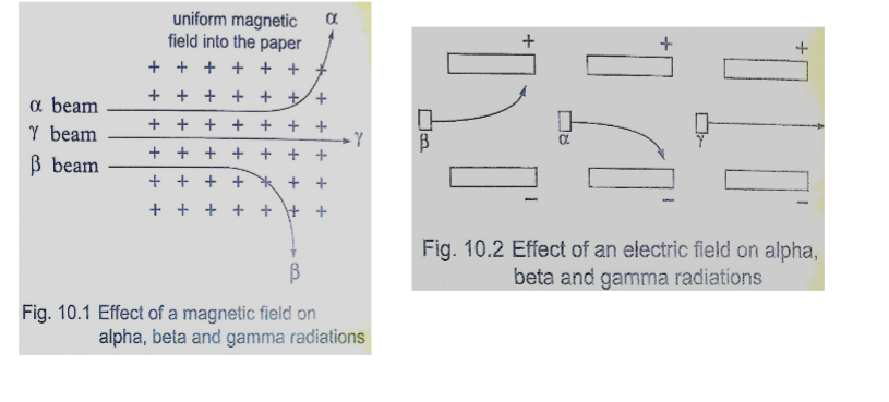
Detecting nuclear radiation
1. Gold leaf electroscope–the rate of collapse of the leaf depends on the nature and intensity of radiation.
The radioactive source ionizes the air around the electroscope. Beta particles discharges a positively charged electroscope with the negative charge neutralizing the charge of the electroscope. Alpha particles would similarly discharge a negatively charged electroscope.
To detect both alpha and beta particles a charged electroscope may not be suitable because their ionization in air may not be sufficiently intense making the leaf not to fall noticeably.
2. The spark counter – the detector is shown below
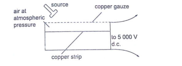
This detector is suitable for alpha sources due to the inadequacy of the ionization by both beta and gamma radiations.
By putting the source away from the gauze or placing a sheet of paper between the two one can determine the range and penetration of the alpha particles.
3. Geiger Muller (GM) tube– it is illustrated as below
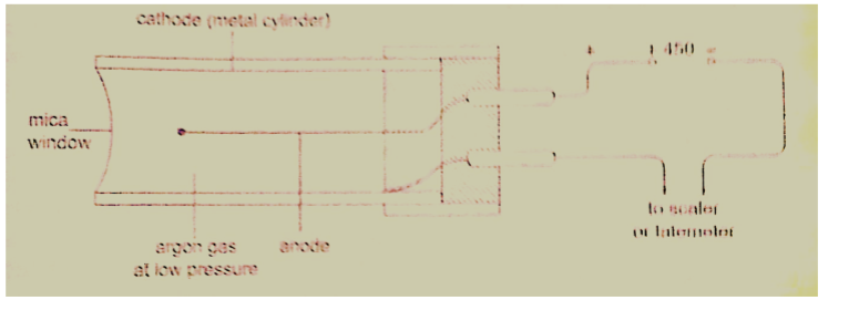
The mica window allows passage of alpha, beta and gamma radiations.
The radiations ionize the gas inside the tube. The electrons move to the anode while the positive ions move to the cathode. As the ions are produced there are collisions which produce small currents which are in turn amplified and passed to the scale.
The scale counts the pulses and shows the total on a display screen.
After each pulse the gas returns to normal ready for the next particle to enter.
A small presence of halogen gas in the tube helps in absorbing the positive ions to reduce further ionization and hence a quick return to normal. This is called quenching the tube.
4. The solid state detector– this detector can be used to detect alpha, beta and gamma radiations where the incoming radiation hits a reverse biased p-n junction diode momentarily conducting the radiation and the pulse of the current is detected using a scaler.
5. The diffusion cloud chamber – this chamber is simplified as shown below
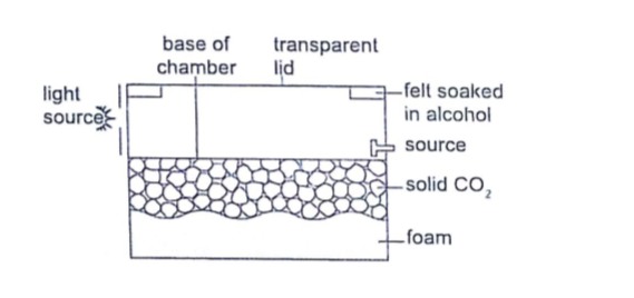
The bottom of the chamber is cooled by solid carbon (V) oxide to around -800 C and the alcohol vapour from the felt ring spreads downwards.
It is cooled below its normal condensing temperature.
As a particle enters the chamber it ionizes the air in its path and alcohol condenses around the path to form millions of tiny alcohol droplets leaving a trail visible because it reflects light from the source.
Alpha particles leave a thick, short straight tracks.
Beta particles leave thin irregular tracks.
Gamma particles do not produce tracks and since they eject electrons from atoms the tracks are similar to those of beta particles.
Activity and half-life of elements
The activity of a sample of radioactive element is the rate at which its constituent nuclei decay or disintegrate.
It is measured in disintegrations per second or Curie (Ci) units, where 1 Ci = 3.7 × 10¹⁰ disintegrations per second
1 micro Curie (µ C) = 3.7 × 10⁴ disintegrations per second.
The law of radioactive decay states that “the activity of a sample is proportional to the number of undecayed nuclei present in the sample”.
The half-life of a radioactive element is the time required for its one-half of the sample to decay.
It is important to note that although the activity approaches zero, it never goes to zero.
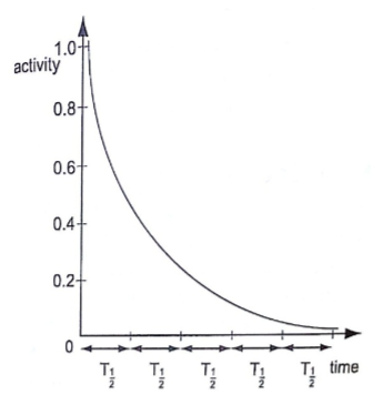
Examples
1. The half-life of a sample of a radioactive substance is 98 minutes.
How long does it take for the activity of the sample to reduce to 1/16th of the original value?
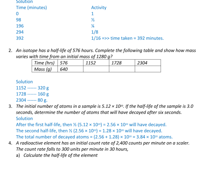
b) If the initial number of atoms in another sample of the same element is 6.0 × 10²⁰, how many atoms will have decayed in 50 hours?
Solution
a) 2,400 × ½ × ½ × ½ = 300
Three half-lives have a total of 30 hours, thus half-life = 30 /3 = 10 hours
b) Since half-life = 10 hrs half-lives in 50 hrs = 50/10 = 5 hrs.
So the remaining undecayed atoms are ½ × ½ × ½ × ½ × ½ × 6.0 × 1020
= 0.1875 × 10²⁰, thus
The number of atoms which have decayed = (6.0 – 0.1875) × 1020
= 5.812 × 10²⁰
Nuclear equations
Particles making an atom can be written using upper and lower subscripts where a proton, ‘p’ with charge +1 and mass 1ᴜ, is written as .
A neutron ‘n’ with no charge but with mass 1ᴜ, is written as , while an electron with a charge of -1 and negligible mass is written as . It is important to note that the principles of conservation apply in radioactive decay.
That means that the total number of nucleons (neutrons + protons) must be the same before and after decay. The L.H.S of the equation must be equal to the R.H.S for both total mass and charge.
Effects of radioactive decay on the nucleus
2. Write an equation to show how a radioactive isotope of cobalt ( o) undergoes a beta decay followed by the emission of gamma rays to form a new nuclide X.
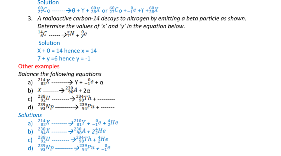
Nuclear fission
Nuclear fission is a process in which a nucleus splits into two or more lighter nuclei. This process generates large amounts of energy together with neutron emission. Nearly 80% of the energy produced appears as kinetic energy of the fission fragments.
For example Uranium-235 undergoes nuclear fission when bombarded with slow neutrons releasing 2-3 neutrons per Uranium molecule and every neutron released brings about the fission of another Uranium-235nuclei.
Another substance which undergoes the same process is Plutonium-239.
Substances which undergo fission directly with slow neutrons are known as fissile substances or isotopes.
Applications of nuclear fission
1. They are used in the manufacture of atomic bombs where tremendous amount of energy is released within a very short time leading to an explosion.
2. When this release of energy is controlled such that it can be released at a steady rate then it is converted into electrical energy hence the principle in nuclear reactors.
Nuclear fusion
Nuclear fusion is the thermal combining of light elements to form relatively heavier nuclei. The process requires very high temperatures for the reacting nuclei to combine upon collision.
These temperatures are provided by ordinary fission bombs.
These reactions sometimes known as thermonuclear reactions.
A fusion reaction releases energy at the rate of 3-23 MeV per fusion event i.e. two deuterium (heavy hydrogen) nuclei to form helium.
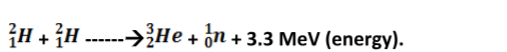
This 3.3 MeV (energy) produced is equal to 5.28 × 10⁻¹³ J.
Application of nuclear fusion
1. Used in the production of hydrogen bomb. Possible reactions for an hydrogen bomb include;
Hazards of radioactivity and their precautions
(i) Due to the ionizing radiation emitted by radiation materials, they affect living cells leading to serious illnesses. Symptoms of radiation exposures are immature births, deformations, retardedness, etc.
(ii) Their exposure to the environment through leaks may lead to environmental pollution leading to poor crop growth and destruction of marine life.
Applications of radioactivity
1. Carbon dating – through the identification of carbon-14 and carbon-12 absorbed by dead plants and animals. Scientists can be able to estimate the age of a dead organism. Since carbon is a radioactive element with a half-life of 5,600 years archeologists can be able to estimate the ages of early life through carbon dating.
2. Medicine – radiation is used in the treatment of cancer, by using a radioactive cobalt-60 to kill the malignant tissue. Radiations are used in taking x-ray photographs using cobalt-60. Radiations are used to sterilize surgical instruments in hospitals.
Radioactive elements can also be used as tracers in medicine where they determine the efficiency of organisms such as kidneys and thyroid glands.
3. Biology and agriculture
– radioactive sources are used to generate different species of plants with new characteristics that can withstand diseases and drought. Insects are sterilized through radiation to prevent the spread of pests and diseases. Potatoes exposed to radiation can be stored for a long time without perishing.
4. Industry – thickness of metal sheets is measured accurately using radiation from radioactive sources. Recently the manufacture of industrial diamonds is undertaken through transmutation.
5. Energy source – in N. America, Europe and Russia nuclear reactors are used to generate electricity.
The amount of fuel used is quite small hence an economical way of generating electricity energy as compared to H.E.P generation.
Chapter Eleven
Electronics
Conductors, insulators and semi-conductors
i) An insulator is a material or object which resists flow of heat (thermal insulator) or electrical charges (electrical insulators). Examples are paraffin, wood, rubber, plastics etc.
ii) Conductors are materials that contain free electrons which carry an electrical charge from one point to another.
Examples are metals and non-metals like carbon, graphite etc.
iii) Semi-conductors are materials or objects which allow the flow of electrical heat or energy through them under certain conditions i.e. temperature. Examples are germanium, silicon, cadmium sulphide, gallium arsenide etc.
Electronic bond structure
This is the series of “allowed” and “forbidden” energy bands that it y bands that it contains according to the band theory which postulates the existence of continuous ranges of energy values (bands) which electron may occupy “allowed” or not occupy ‘forbidden”.
According to molecular orbital theory, if several atoms are brought together in a molecule, their atomic orbitals split, producing a number of molecular orbitals proportional to the number of atoms.
However when a large number of atoms are brought together the difference between their energy levels become very small, such that some intervals of energy contain no orbitals and this theory makes an assumption that these energy levels are as numerous as to be indistinct.
Number, size and spacing of bands.
Any solid has a large number of bands (theoretically infinite). Bands have different widths based upon the properties of the atomic orbitals from which they arise. Bands may also overlap to produce a bigger single band.
Valence and conduction bands
Valence band is the highest range of electron energies where electrons are normally present at zero temperature.
Conduction band is the range of electron energy higher than that of the valence band sufficient to make electrons free (delocalized); responsible for transfer of electric charge. Insulators and semi-conductors have a gap above valence band followed by conduction band above it. In metals, the conduction band is the valence band.
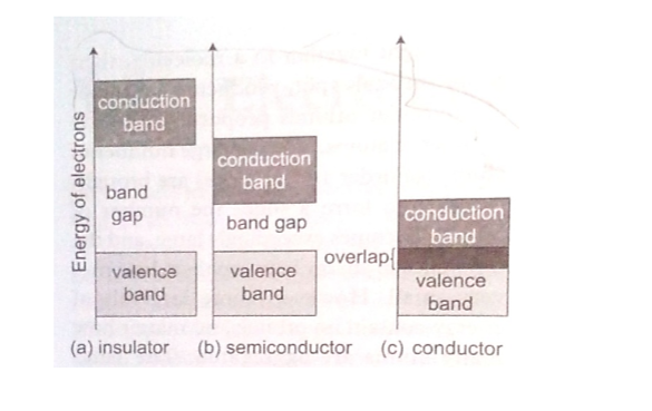
Band structure of a semi-conductor.
Electrons in the conduction band break free of the covalent bonds between atoms and are free to move around hence conduct charge.
The covalent bonds have missing electrons or ‘holes’ after the electrons have moved.
The current carrying electrons in the conduction band are known as free electrons.
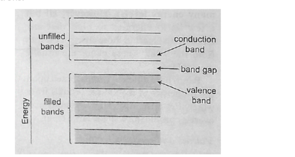
Doping of semi-conductors
Doping is the introduction of impurities in semi-conductors to alter their electronic properties.
The impurities are called dopants. Doping heavily may increase their conductivity by a factor greater than a million.
Intrinsic and extrinsic semi-conductors
An intrinsic semi-conductor is one which is pure enough such that the impurities in it do not significantly affect its electrical behavior.
Intrinsic semi-conductors increase their conductivity with increase in temperature unlike metals.
An extrinsic semi-conductor is one which has been doped with impurities to modify its number and type of free charge carriers present.
N-type semi-conductors
In this case the semi-conductor is given atoms by an impurity and this impurity is known as donor so it is given donor atoms (donated).
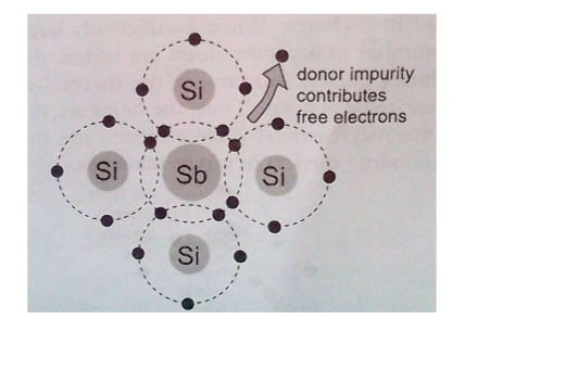
P-type semi-conductors
The impurity within the semi-conductor accepts atoms with free electrons (dopants). This forms a ‘hole’ within the semi-conductors.

Junction diodes
Junction refers the region where the two types of semi-conductors meet. The junctions are made by combining an n-type and p-type semi-conductor. The n-region is the cathode and the p-region is the anode.
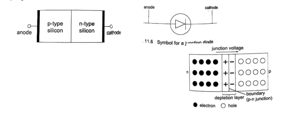
Forward bias of a p-n junction
It occurs when the p-type block is connected to the positive terminal and the n-type block is connected to the negative terminal of a battery.
The depletion layer of the junction reduces to be very thin to allow the flow of electric current.
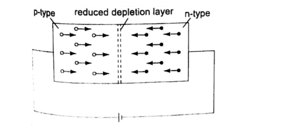
Reverse bias of a p-n junction
The negative terminal of the battery is connected to the p-type region while the n-type isconnected to positive terminal.
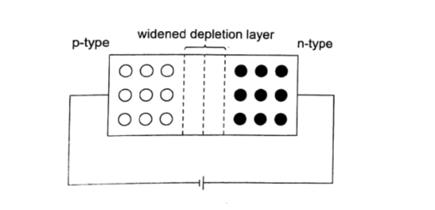
The depletion layer widens and resists the flow of electrons to minimal or zero (no currentflowing through) when the electric field increases beyond critical point the diode junction eventually breaks down and at this voltage it is referred to as the breakdown voltage. Diodes are intended to operate below the breakdown voltage.
Applications of junction diodes
They are mainly used for rectification of a.c. current for use by many electrical appliances. Rectification is the conversion of sinusoidal waveform into unidirectional (non-zero) waveform.
Half wave rectification
In this case the first half cycle of a sinusoidal waveform is positive and the inclusion of a reverse biased diode makes the current not to flow to the negative side of the wave.
The current therefore conducts on every half cycle hence a half wave rectification is achieved.
The voltage is d.c. and always positive in value though it is not steady and needs to be smoothed by placing a large capacitor in parallel to the load as shown.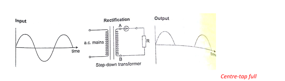
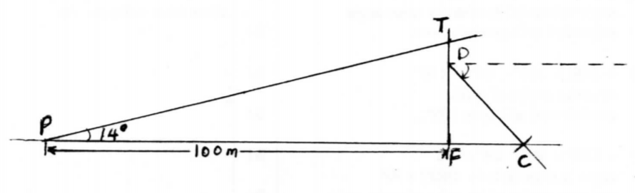
Radio transmitter and receiver
Radio waves are produced by circuits that make electrons vibrate and they are known as oscillators which produce varied frequencies. Since radio waves have greater range in air than sound or even light waves they are used as carriers of audio (sound) and visual information (TV) waves.
The sound is first changed into electrical vibrations by use of a microphone or other device then added to the radio carrier wave and this changes the amplitude of the carrier and is called amplitude modulation.
The modulated wave is given out by the transmitting aerial and received by another aerial in a radio or TV when they cause vibrations between the earth and the aerial.
They are then demodulated by a diode and hence heard as a sound or image.
 Grade 5 Free, Updated CBC Schemes Of Work Free (Term 1, 2 and 3)